Deposition device and atomic layer deposition equipment

A deposition device and deposition body technology, applied in coating, metal material coating process, gaseous chemical plating, etc., can solve the problems of cross-contamination, incomplete coating of ALD deposition particles, etc., and achieve the effect of solving cross-contamination

A deposition device and deposition body technology, applied in coating, metal material coating process, gaseous chemical plating, etc., can solve the problems of cross-contamination, incomplete coating of ALD deposition particles, etc., and achieve the effect of solving cross-contamination

CN109680263APending Publication Date: 2019-04-26SHENZHEN YUANSU OPTOELECTRONICS TECH CO LTD

Image

  • Deposition device and atomic layer deposition equipment
  • Deposition device and atomic layer deposition equipment
  • Deposition device and atomic layer deposition equipment

Examples


Embodiment Construction

[0027] The following will clearly and completely describe the technical solutions in the embodiments of the present invention in conjunction with the accompanying drawings of the embodiments of the present invention. Obviously, the described embodiments are only part of the embodiments of the present invention, not all of them. Based on the embodiments of the present invention, other embodiments obtained by those skilled in the art without creative efforts all fall within the protection scope of the present invention.

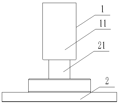
[0028] figure 1 As an embodiment of the present invention, this embodiment provides a deposition device, the deposition device includes:

[0029] A reaction unit, comprising a shell 1 with a hollow structure, the hollow structure forms a reaction chamber 11 for depositing the object to be deposited;

[0030] The supply unit 2 communicates with the reaction chamber 11, and the supply unit 2 includes a reactant delivery module 21;

[0031] Wherein, the reactant...


PUM


Abstract

The invention provides a deposition device. In the deposition device, a hollow shell is used as a reaction cavity. The deposition device comprises a supply unit communicating with the reaction cavity,wherein the supply unit comprises a reactant conveying module which is detachably connected to a reaction unit. Atomic layer deposition equipment comprises a rack and the deposition device and can beused for preparing powder surface coating layers. The atomic layer deposition equipment can effectively solve the problems of cross contamination and incomplete ALD (atomic layer deposition) particlecoating layers occurring when different thin film materials are deposited.

Description

technical field [0001] The invention relates to the field of thin film deposition, in particular to a deposition device and atomic layer deposition equipment. Background technique [0002] Particle surface functionalization is an important part of material surface engineering technology, and it is of great significance to improve the original performance of particles. For example, nano-silver particles have good thermal conductivity, electrical conductivity, and surface plasmon resonance effect. Wrapping nano-silver particles in carbon nanotubes (CNTs@Ag) can enhance the photoelectric performance of matrix carbon nanotubes; in the catalyst The surface of the particles is coated with a protective layer, which can effectively prevent the metal catalysts from agglomerating during the sintering process, resulting in a decrease in catalytic performance or even loss of catalytic performance. [0003] Common methods for particle surface functionalization include sol-gel method (So...

Claims


Application Information

Patent Timeline
26 Apr 2019
Publication
CN109680263A
IPC
C23C16/455
CPC
C23C16/4417; C23C16/45525
Inventors
李哲峰; 郑文岸