
Fan control device and method

A fan control and controller technology, applied in pump control, non-variable pumps, machines/engines, etc., can solve problems such as CPLD pin tension

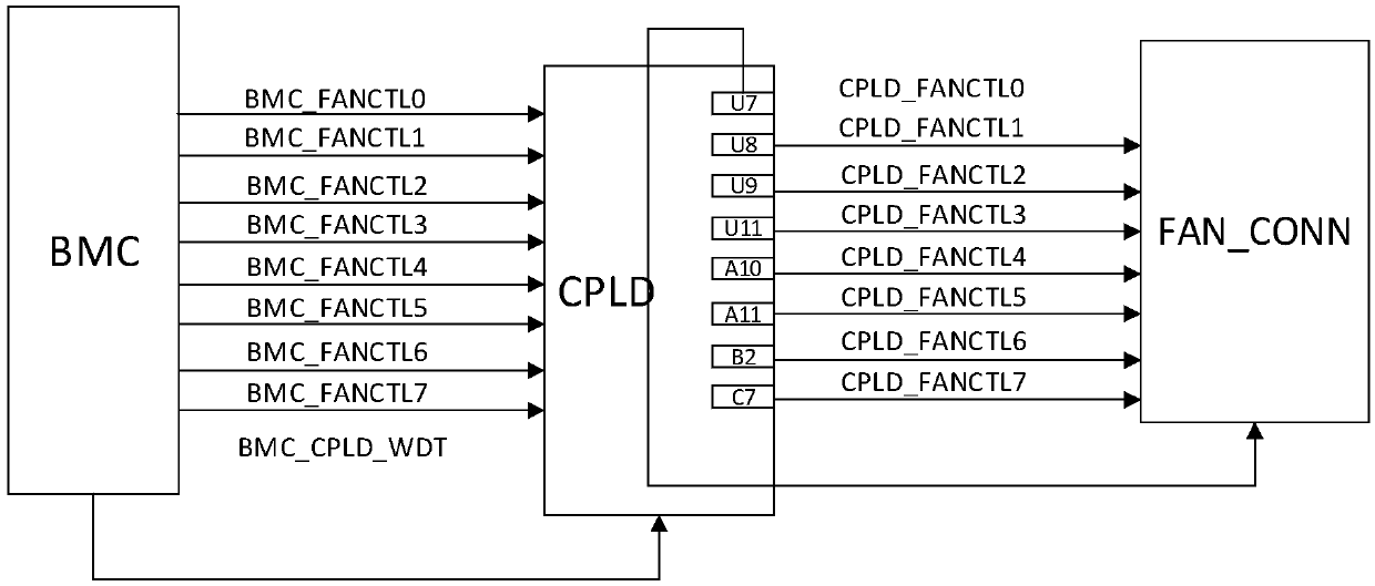
Inactive Publication Date: 2019-04-26
ZHENGZHOU YUNHAI INFORMATION TECH CO LTD
View PDF6 Cites 12 Cited by
  • Summary
  • Abstract
  • Description
  • Claims
  • Application Information

AI Technical Summary

Problems solved by technology

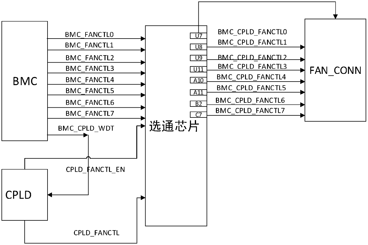
The fan control signal is transmitted through the gate chip, and the CPLD only controls the gate chip, which greatly reduces the occupation of CPLD pins and solves the problem of CPLD pin tension

Method used


Image

  • Fan control device and method
  • Fan control device and method
  • Fan control device and method

Examples


Embodiment Construction

[0030] In order to make the purpose, technical solution and advantages of the present invention more clear, the embodiments of the present invention will be described in detail below in conjunction with the accompanying drawings. It should be noted that, in the case of no conflict, the embodiments in the present application and the features in the embodiments can be combined arbitrarily with each other.

[0031] The steps shown in the flowcharts of the figures may be performed in a computer system, such as a set of computer-executable instructions. Also, although a logical order is shown in the flowcharts, in some cases the steps shown or described may be performed in an order different from that shown or described herein.

[0032] The current main method of fan regulation is that BMC detects the temperature of each point inside the chassis, and uses PWM dedicated control pins to control the fan speed. The signal passes from BMC to CPLD, and then to the fan interface. When CPL...


PUM


Abstract

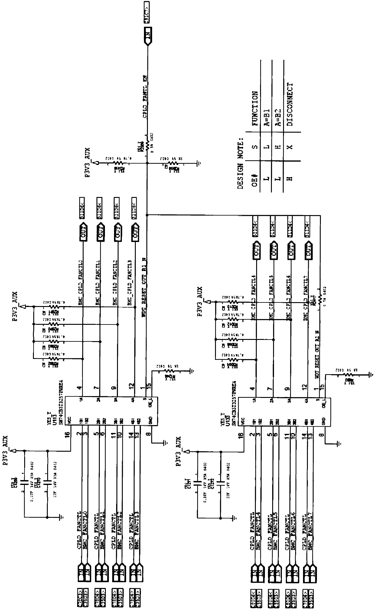
The invention discloses a fan control device and method, relates to an electronic hardware technology, and solves the problem of tensioning of complex programmable logic device (CPLD) pins. The devicecomprises a base-board management controller (BMC) and a CPLD and further comprises a gate chip; the gate chip comprises multiple fan control signal input pins used for receiving fan control signalsoutput by the BMC; the gate chip further comprises multiple fan control signal output pins; each fan control signal output pin is connected with a fan; the gate chip further comprises a control pin; and the CPLD is connected with the control pin and is used for sending gate control signals for controlling the various fan control signal output pins to the control pin. According to the technical scheme, the device and the method are applicable to server circuit design, and the fan control scheme which occupy a few CPLD pins is realized.

Description

technical field [0001] The invention relates to electronic hardware technology, in particular to a fan control device and method. Background technique [0002] With the development of Intel's new-generation Whitely platform, the number of signals is increasing, and complex programmable logic devices (CPLDs) need to process more and more signals, resulting in tight pins. If the CPLD model is simply upgraded, the cost will increase. [0003] The current main method of fan regulation is that the baseboard management controller (BMC) detects the temperature of each point inside the chassis, and uses PWM dedicated control pins to control the fan speed. The signal passes from the BMC through the CPLD to the fan interface. When the BMC hangs up, the CPLD actively controls each fan, and generally the speed is adjusted to 80% or 100%. If there are 8 fans, 16 pins of the CPLD will be occupied, causing tension on the pins of the CPLD. Contents of the invention [0004] In order to s...

Claims


Application Information

Patent Timeline
Patent Type & Authority Applications(China)
IPC IPC(8): F04D27/00
CPCF04D27/00
Inventor 刘纪斌董超赵伟涛
Owner ZHENGZHOU YUNHAI INFORMATION TECH CO LTD
Learn More