Equipotential field protection device

A protection device and equipotential technology, applied in the direction of overload protection device, measuring device, measuring electricity, etc., can solve the problems that the staff cannot get early warning, current leakage and so on

Inactive Publication Date: 2019-04-26
YUNNAN POWER GRID CO LTD PUER POWER SUPPLY BUREAU
View PDF5 Cites 2 Cited by
  • Summary
  • Abstract
  • Description
  • Claims
  • Application Information

AI Technical Summary

Problems solved by technology

[0005] This application provides an equipotential field protection device to solve the technical pr

Method used


Image

  • Equipotential field protection device
  • Equipotential field protection device
  • Equipotential field protection device

Examples


Embodiment Construction

[0020] In order to enable those skilled in the art to better understand the technical solutions in the present application, the technical solutions in the embodiments of the present application will be clearly and completely described below in conjunction with the drawings in the embodiments of the present application. Obviously, the described The embodiments are only some of the embodiments of the present application, not all of them. Based on the embodiments in this application, all other embodiments obtained by persons of ordinary skill in the art without creative efforts shall fall within the scope of protection of this application.

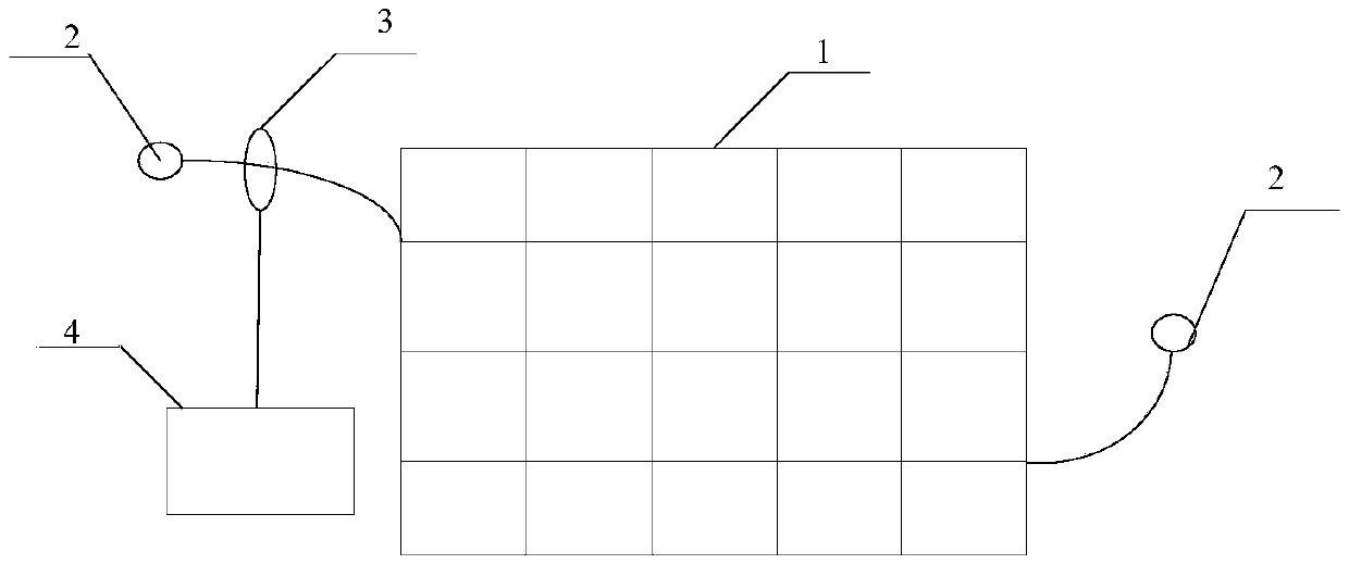
[0021] Such as figure 1 As shown, it is a schematic structural diagram of an equipotential field protection device provided by the embodiment of the present application. The embodiment of the present application provides an equipotential field protection device including: a potential protection module 1, a current sensor 3 and an alarm module...


PUM


Abstract

The invention discloses an equipotential field protection device, which comprises a potential protection module, a current sensor and an alarm module, wherein the potential protection module comprisestwo insulating protective layers, a conductive grid layer is clamped between the two insulating protective layers; the conductive grid layer is provided with at least two symmetrically arranged electrode leading-out ends, the electrode leading-out ends are communicated with a grounding wire to form a loop, the current sensor is arranged between the conductive grid layer and the electrode leading-out ends, and the current sensor is electrically connected with the alarm module. When a large current accident occurs, the step voltage is generated, the current at the electrode leading-out end is induced inside the conductive grid layer through a larger current and the current sensor, the current is converted into a voltage value, the alarm module is driven to generate early warning, and the formed step voltage is subjected to the early warning function, so that an operator can know the danger, guide the operator to pay attention as soon as possible, and concentrate on checking the potential safety hazard, thereby reducing the personal harm.

Description

technical field [0001] The present application relates to the technical field of leakage protection, in particular to an equipotential field protection device. Background technique [0002] When carrying out live work in substations or outdoors, it is usually necessary to use relevant testing equipment for live operation. For example, when carrying out partial discharge tests, it is necessary to connect the high-frequency CT with the grounding circuit while carrying out live inspections. It may occur that the operator may touch the housing of live equipment or adjacent equipment. [0003] If the detected equipment or adjacent equipment has failed, and the operator is unknown in advance, it is possible that the enclosure equipment will be charged. Even if the operator uses non-basic equipment for detection, the overcurrent signal generated by the fault current to the ground may cause the ground surface potential to rise, resulting in increased step voltage, which constitutes...

Claims


Application Information

Patent Timeline
IPC IPC(8): G01R1/36G01R31/02
CPCG01R1/36G01R31/50
Inventor 李卫朱兴柯杨玉兵徐斌史俊苏煜李洪伟李文亮聂瑛李学妨兰天刘华文黄虹周娅陈秋涛罗巍徐良涛刘荣胜孙遥孙帅伟
Owner YUNNAN POWER GRID CO LTD PUER POWER SUPPLY BUREAU
Why Eureka
Try Eureka