A modeling method for a blade tip process extension section of a rotor blade forge piece

A technology of rotor blade and modeling method, which is applied in the direction of instrumentation, design optimization/simulation, calculation, etc., can solve the problems of large springback deformation, affecting the positioning accuracy of blade machining, and large fitting error of positioning point K3 of the tip section. , to achieve the effect of accurate calculation

Active Publication Date: 2019-04-26
CHINA HANGFA GUIZHOU LIYANG AVIATION POWER CO LTD
View PDF6 Cites 3 Cited by
  • Summary
  • Abstract
  • Description
  • Claims
  • Application Information

AI Technical Summary

Problems solved by technology

This method will cause the transition of the extension section to be unsmooth, which will mainly affect the blade in three aspects: 1. The positioning point K3 of the tip section has a large fitting error, which affects the positioning accuracy of the subsequent machining of the blade; 2. At the tip section There is stress concentration, the rebound deformation of the forging is large after forging, and the contour, torsion angle and bending of several sections near the tip are not easy to guarantee; 3. It affects the fluidity of the metal, and there is stress concentration at the transfer point, which in turn affects the life of the die

Method used


Image

  • A modeling method for a blade tip process extension section of a rotor blade forge piece
  • A modeling method for a blade tip process extension section of a rotor blade forge piece
  • A modeling method for a blade tip process extension section of a rotor blade forge piece

Examples


Embodiment

[0025] Embodiment: the purpose of the invention is achieved by the following technical solutions:

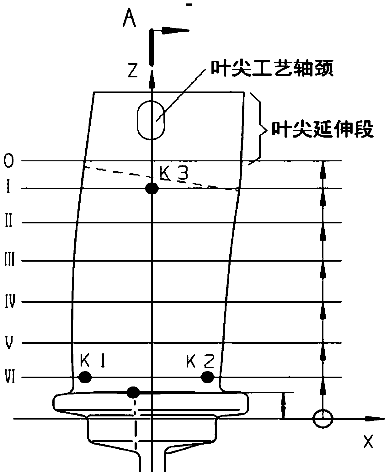
[0026] 1. Analyze the airfoil shape line data: according to the airfoil coordinate representation format specified in HB5647-98 "Blade Airfoil Labeling, Tolerance and Airfoil Surface Roughness", the blade body shape line coordinate points in the blade design drawing Automatic analysis, the analysis process is integrated in the UG plug-in, the technology used for analysis is the mainstream analysis tool: regular expression, java language provides a regex development kit that can perfectly support regular expressions, and can accurately and conveniently analyze leaf points coordinate.

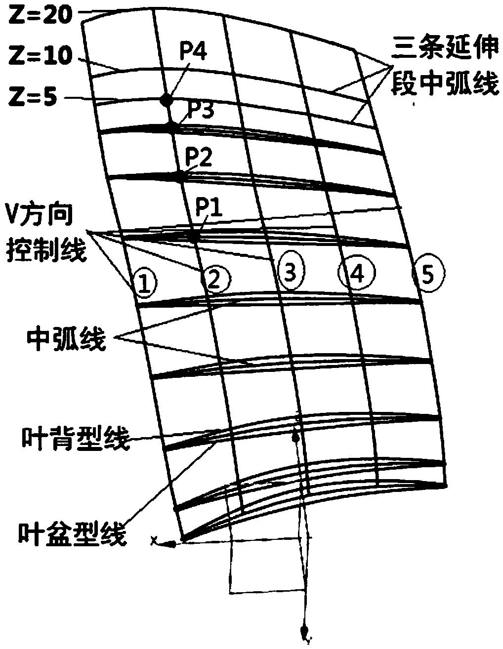
[0027] 2. Calculating the center arc: Calculate the center arc of each blade body section according to the point coordinates obtained by analysis. The center arc is used to observe the trend and does not require high precision. The leaf pot and the leaf back shape line of the body are divided into...


PUM


Abstract

The invention discloses a modeling method for a blade tip process extension section of a rotor blade forging. The modeling method comprises the following steps: 1, analyzing blade body molded line data; 2, calculating a middle arc line; 3, making a trend control line in the blade spreading direction; 4, calculating a mean camber line of the extension section; 5, calculating blade basins and bladeback molded lines of the three control lines of the extension section; And 6, smoothing each section molded line. According to the modeling method for the extension section of the blade body of the precision forging blade without allowance design, the profile tolerance, the torsion angle and the bending of the tip part of the blade and the blade spreading waviness of the whole blade body can be better guaranteed.

Description

Technical field [0001] The invention relates to the forging design of the rotor blade of an aero-engine compressor, in particular to the design of the blade tip extension section. Background technique [0002] The blade tip extension section of the rotor blade forging raw material is based on the structural characteristics of the blade design. In order to meet the requirements of the forging process, the technological positioning journal is placed, and the part that extends 10mm to 20mm at the blade tip according to the blade shape trend. The blade forging is shown in the figure figure 1 shown. [0003] At present, most of the blade forging drawings are designed with the three-dimensional drawing software UG. When dealing with the blade tip extension section, the blade tip section is copied upwards by 10mm to 20mm, and then the copied section is translated and rotated according to the trend, and finally the "passing curve Group" command to get the leaf body entity. This me...

Claims


Application Information

Patent Timeline
Patent Type & Authority Applications(China)
IPC IPC(8): G06F17/50
CPCG06F30/20
Inventor 黄联杰胡吉云吴永斌陈玉珍陆彦良王宏操
Owner CHINA HANGFA GUIZHOU LIYANG AVIATION POWER CO LTD
Why Eureka
Try Eureka