
Inductively coupled power transfer (ICPT) system resonance compensation parameter optimization method considering parallel transfer of signals and electric energy

A technique for compensating parameters and optimizing methods, which is applied to electrical components, circuit devices, etc., can solve problems such as non-negligible influence and low power transmission efficiency, and achieve the effects of accurate modeling and improved power transmission efficiency

Active Publication Date: 2019-04-26
LANZHOU JIAOTONG UNIV
View PDF5 Cites 6 Cited by
  • Summary
  • Abstract
  • Description
  • Claims
  • Application Information

AI Technical Summary

Problems solved by technology

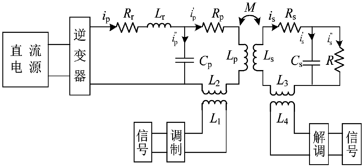
Power transmission in ICPT systems is often accompanied by signal transmission requirements. Using power transmission channels for signal transmission can achieve high-speed signal transmission, but the impact of signal transmission on power transmission under the shared channel cannot be ignored. At present, power transmission based on ICPT systems In the field of synchronous signal transmission, the optimization of the resonance parameters of the system only considers the power transmission itself, but does not consider the influence of the signal coupling coil in the signal transmission circuit, so there is a problem of low power transmission efficiency

Method used


Image

  • Inductively coupled power transfer (ICPT) system resonance compensation parameter optimization method considering parallel transfer of signals and electric energy
  • Inductively coupled power transfer (ICPT) system resonance compensation parameter optimization method considering parallel transfer of signals and electric energy
  • Inductively coupled power transfer (ICPT) system resonance compensation parameter optimization method considering parallel transfer of signals and electric energy

Examples


Embodiment Construction

[0040] The preferred embodiments of the present invention will be described below in conjunction with the accompanying drawings. It should be understood that the preferred embodiments described here are only used to illustrate and explain the present invention, and are not intended to limit the present invention.

[0041] An ICPT system resonance compensation parameter optimization method considering parallel transmission of signals and electric energy, including:

[0042] Establish a mathematical model based on the current relationship between the main road of the primary and secondary sides of the ICPT system and each branch and the current relationship between the branches, the impedance of the primary and secondary sides of the ICPT system, the output, input power and power transmission efficiency of the ICPT system;

[0043] selecting an objective function based on the mathematical model;

[0044] determining constraints on the objective function;

[0045] The resonance ...


PUM


Abstract

The invention discloses an inductively coupled power transfer (ICPT) system resonance compensation parameter optimization method considering parallel transfer of signals and electric energy. The optimization method comprises the steps that based on the current relationship between primary and secondary side main circuits and branches and the current relationship between the branches in the ICPT system, the impedance of primary and secondary sides in the ICPT system and the output and input power and the electric energy transfer efficiency in the ICPT system, a mathematical model is established; an objective function is selected based on the mathematical model; a constraint condition of the objective function is determined; based on the mathematical model, the objective function, and the constraint condition, the resonance compensation parameters of the ICPT system are optimized. In the optimization design of the ICPT system parameters with synchronous transfer of the electric energy and the signals, the influence after the introduction of a signal transmission circuit is fully considered, the modeling is more accurate, and great convenience is provided for the research work such asresonance compensation parameter optimization, so that the purpose of improving the electric energy transfer efficiency is achieved.

Description

technical field [0001] The invention relates to the field of wireless power transmission, in particular to a method for optimizing resonance compensation parameters of an ICPT system considering parallel transmission of signals and electric power. Background technique [0002] As a new type of power supply, the Inductively Coupled Power Transfer (ICPT) system has gradually realized short-distance high-power wireless power transmission, mobile ICPT system power transmission and multi-load ICPT system power transmission, so it is more and more popular. extensive attention. Power transmission in ICPT systems is often accompanied by signal transmission requirements. Using power transmission channels for signal transmission can achieve high-speed signal transmission, but the impact of signal transmission on power transmission under the shared channel cannot be ignored. At present, power transmission based on ICPT systems In the field of synchronous transmission with signals, the...

Claims


Application Information

Patent Timeline
Patent Type & Authority Applications(China)
IPC IPC(8): H02J50/12
CPCH02J50/12
Inventor 李欣赵乐李若琼董海鹰张蕊萍李帅兵
Owner LANZHOU JIAOTONG UNIV
Learn More