Rotor sealing structure of locomotive permanent magnet synchronous traction motor

A permanent magnet synchronous, traction motor technology, applied in the magnetic circuit shape/style/structure, electromechanical device, magnetic circuit, etc., can solve the problems of poor cooling effect, complex cooling system structure, etc., to eliminate potential safety hazards and reduce technical risks , Guarantee the effect of safe and reliable operation

Active Publication Date: 2019-04-26
CRRC YONGJI ELECTRIC CO LTD
View PDF4 Cites 7 Cited by
  • Summary
  • Abstract
  • Description
  • Claims
  • Application Information

AI Technical Summary

Problems solved by technology

[0013] The present invention provides a rotor sealing structure for locomotive permanent magnet synchronous traction motors in order to solve the techni

Method used


Image

  • Rotor sealing structure of locomotive permanent magnet synchronous traction motor
  • Rotor sealing structure of locomotive permanent magnet synchronous traction motor
  • Rotor sealing structure of locomotive permanent magnet synchronous traction motor

Examples


Embodiment Construction

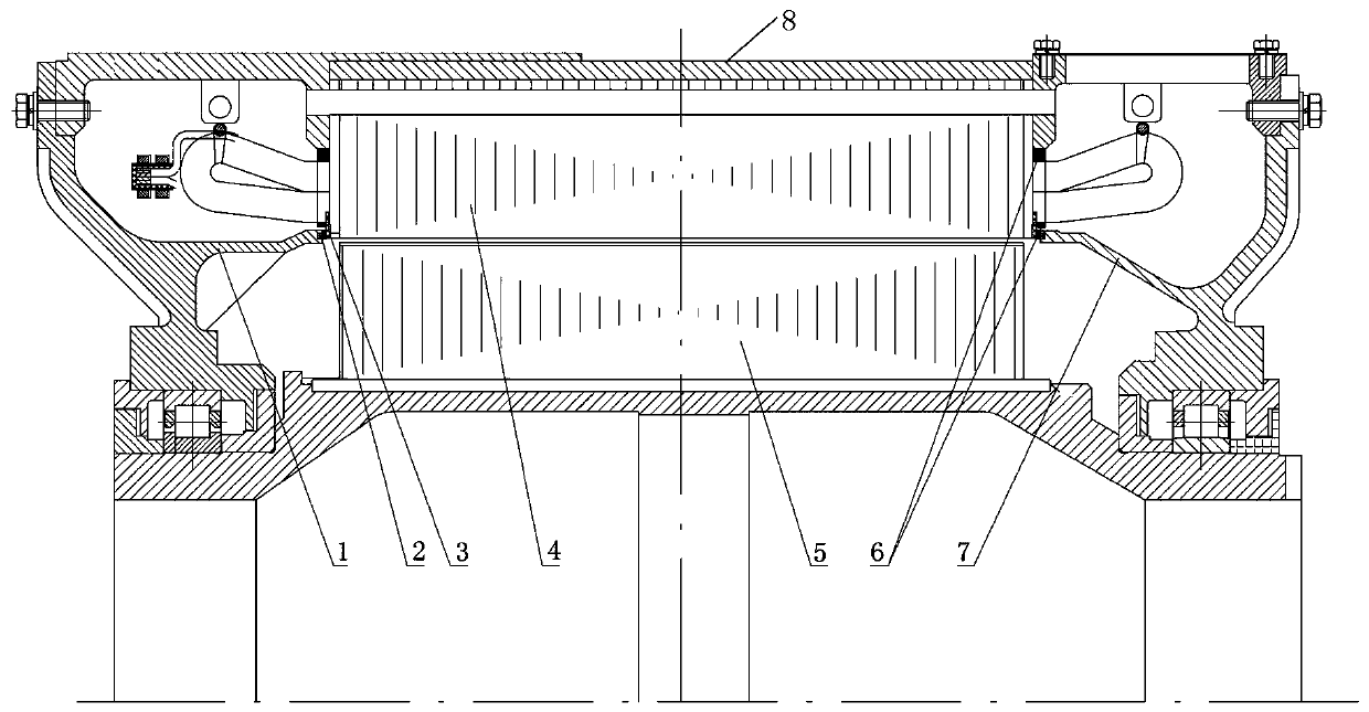
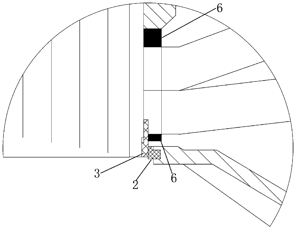
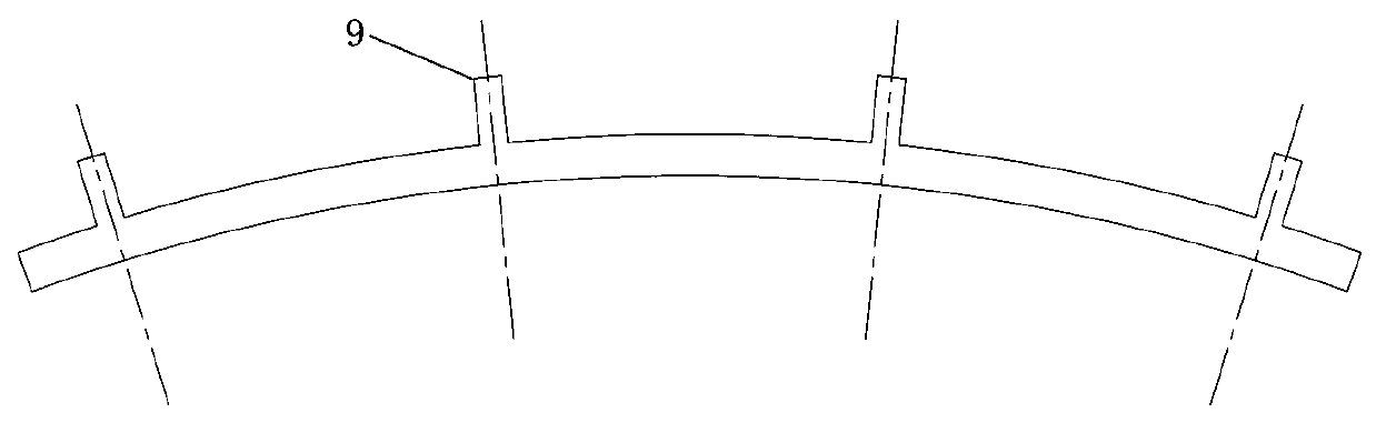
[0029] A rotor sealing structure for a permanent magnet synchronous traction motor of a locomotive, comprising a frame, a rotor core, a stator core, a non-drive end cover, and a drive end cover; the inner sides of the non-drive end cover and the drive end cover both extend toward the inside of the motor And respectively press and butt with the end plates on both sides of the stator core near the inner circle; the end faces of the extension structure of the non-drive end cover and the drive end cover are fixed with sealing strips, and there are fixed installations between the sealing strips and the stator end plates. Ring-shaped sealing plate; there are several tooth-shaped structures evenly distributed on the outside of the annular sealing plate, the tooth-shaped structures correspond to the stator slots, and the tooth-shaped structures are fastened to the stator end plate by sealant, and then cooperate with the sealing strip Seal the rotor core.

[0030] There is an annular g...


PUM


Abstract

The invention relates to a permanent magnet motor sealing technology, in particular to a rotor sealing structure of a locomotive permanent magnet synchronous traction motor. The technical problems that the cooling effect of a machine shell of an existing permanent magnet motor is poor, and a matched cooling system is complex in structure are solved. The rotor sealing structure of the locomotive permanent magnet synchronous traction motor comprises a machine base, a rotor iron core, a stator iron core, a non-transmission end cover and a transmission end cover; the inner sides of the non-transmission end cover and the inner side of the transmission end cover extend towards the inside of the motor and are in compression butt joint with the positions, close to the inner circle, of end plates at the two sides of the stator iron core; sealing strips are fixed between the extending structures of the non-transmission end cover and the transmission end cover and the stator end plates, annular sealing plates are further arranged between the sealing strips and the stator end plates, and then the rotor iron core is sealed by the sealing plates and the sealing strips together. According to therotor sealing structure, cooling air cannot enter a rotor part, so that foreign matter in the cooling air is prevented from being adsorbed on the surface of a rotor, and the technical risk caused whena locomotive motor uses a permanent magnet motor is reduced.

Description

technical field [0001] The invention relates to a sealing technology of a permanent magnet motor, in particular to a rotor sealing structure of a permanent magnet synchronous traction motor of a locomotive. Background technique [0002] Permanent magnet synchronous motors have the advantages of high efficiency, high energy density, and strong overload capacity. Countries around the world are actively developing permanent magnet synchronous motor traction systems. The existing locomotive traction system adopts the asynchronous traction motor, which is cooled by forced ventilation. After the power supply of the asynchronous motor is turned off, the magnetic field disappears, and the forced ventilation continues to blow out the dust in the motor. If the permanent magnet synchronous motor of the locomotive adopts an air-cooled structure, the existing forced ventilation cooling system of the locomotive can be used, and only the layout of the cooling air duct of the motor needs to...

Claims


Application Information

Patent Timeline
IPC IPC(8): H02K5/20H02K5/04H02K5/10H02K1/16H02K9/00
CPCH02K1/165H02K5/04H02K5/10H02K5/20H02K9/00
Inventor 孙德强任延生吴楠倪伟张江涛
Owner CRRC YONGJI ELECTRIC CO LTD
Why Eureka
Try Eureka