Cabinet
A technology for cabinets and cabinet doors, which is applied in the field of cabinets with expandable heat dissipation capacity. It can solve the problems of waste and waste of temperature control components, and the heat dissipation capacity of the cabinet cannot meet the upgrade requirements, so as to achieve the effect of satisfying the heat dissipation capacity and improving the heat dissipation capacity.
- Summary
- Abstract
- Description
- Claims
- Application Information
AI Technical Summary
Problems solved by technology
Method used
Image

Examples
Embodiment 1
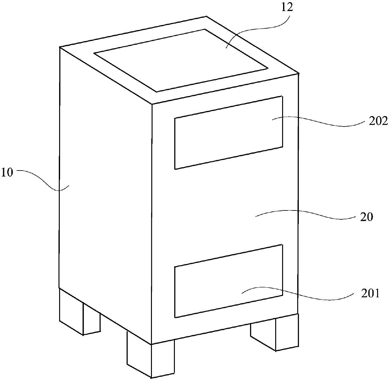
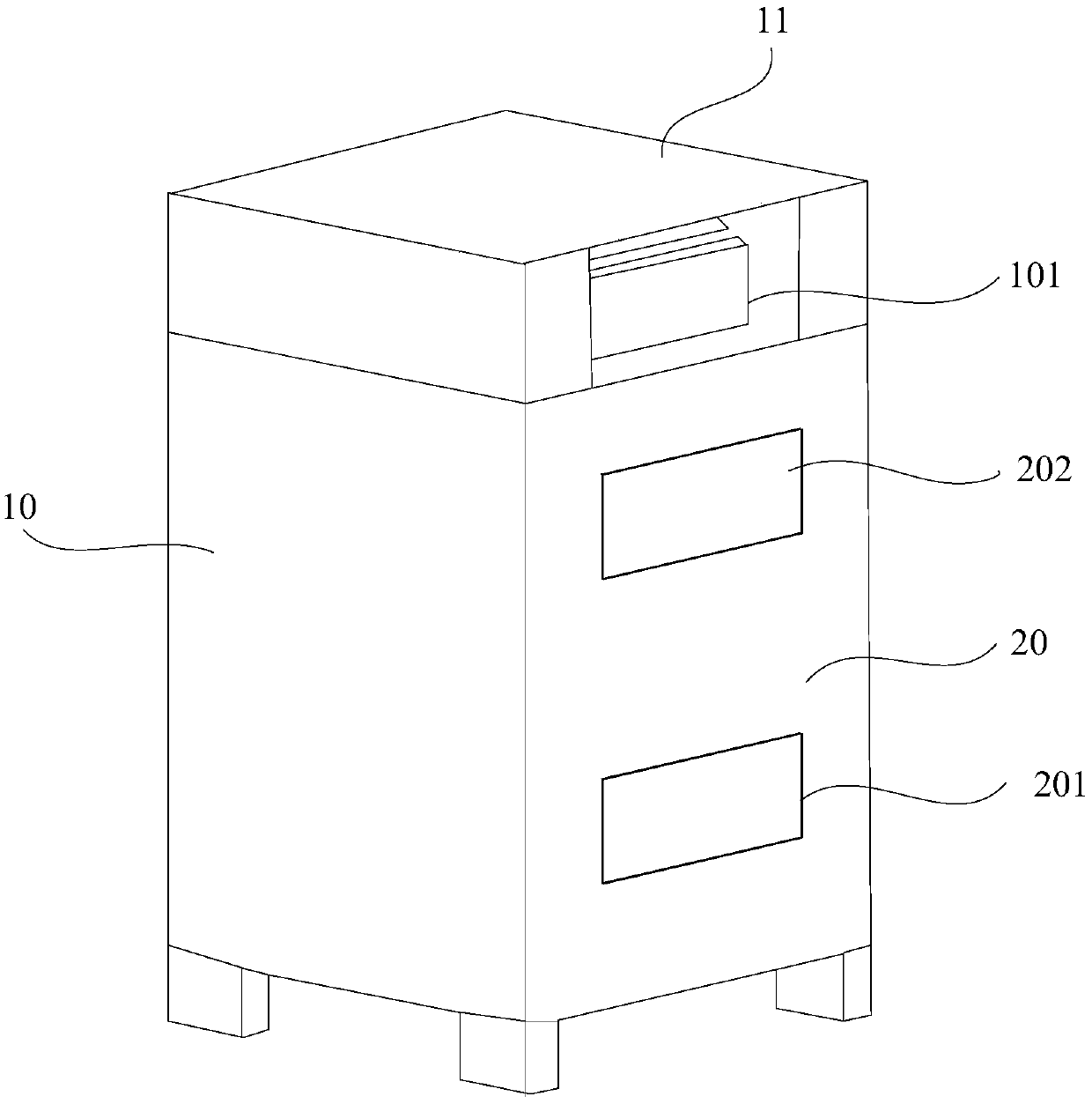
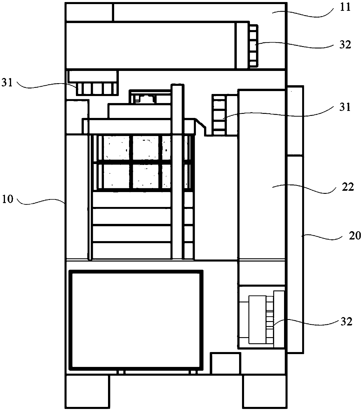
[0053] Figure 1A It is a three-dimensional schematic diagram of the cabinet provided in Embodiment 1 of the present application, Figure 1B It is another perspective schematic diagram of the cabinet provided in Embodiment 1 of the present application, Figure 1C It is a side sectional structural schematic diagram of the cabinet provided in Embodiment 1 of the present application, Figure 1D It is a structural schematic diagram of the air flow direction in the internal and external circulation air ducts of the temperature control components on the cabinet provided in Embodiment 1 of the present application. Figure 1E It is another structural schematic diagram of the cabinet provided in Embodiment 1 of the present application.
[0054] As mentioned in the background technology, the existing outdoor cabinets have the problems of waste of temperature control components and the inability to meet the upgrading requirements of heat dissipation capacity. , once the heat dissipatio...
Embodiment 2
[0081] figure 2 It is a structural schematic diagram of the air flow direction in the internal and external circulation air ducts of the temperature control component in the front view of the cabinet provided in Embodiment 2 of the present application.
[0082] In this example, if figure 2 As shown, specifically, the first-level temperature control component 11 is set on the top of the cabinet body 10, and the second-level temperature control component 22 is set on the cabinet door 20 as an example. Specifically, in this embodiment, the first internal circulation The air duct and the first outer circulation air duct are two air ducts with intersecting wind flow directions, that is, the flow direction 111 of the hot air in the first inner circulation air duct crosses the flow direction 112 of the cold air in the first outer circulation air duct, for example, with The cabinet door 20 is the front. At this time, the flow direction 111 of the hot air in the first inner circulat...
Embodiment 3
[0084] Figure 3A It is a structural schematic diagram of the air flow direction in the internal and external circulation air ducts of the temperature control components in the front view of the cabinet provided in Embodiment 3 of the present application, Figure 3B It is another schematic structural diagram of the air flow direction in the internal and external circulation air ducts of the temperature control components in the front view of the cabinet provided in Embodiment 3 of the present application, Figure 3C It is another structural schematic diagram of the air flow direction in the internal and external circulation air ducts of the temperature control component in the front view of the cabinet provided in Embodiment 3 of the present application.
[0085] The difference between the cabinet provided in this embodiment and the above embodiment is: in this embodiment, if Figure 3C As shown, the first inner circulation air duct and the first outer circulation air duct ar...
PUM
 Abstract
Description
Claims
Application Information
 - R&D
- Intellectual Property
- Life Sciences
- Materials
- Tech Scout
- Unparalleled Data Quality
- Higher Quality Content
- 60% Fewer Hallucinations
Browse by: Latest US Patents, China's latest patents, Technical Efficacy Thesaurus, Application Domain, Technology Topic, Popular Technical Reports.
© 2025 PatSnap. All rights reserved.Legal|Privacy policy|Modern Slavery Act Transparency Statement|Sitemap|About US| Contact US: help@patsnap.com