Split torque transmission deceleration device for helicopters

A technology of split-torsion transmission and deceleration device, which is applied in transmission devices, gear transmission devices, mechanical equipment, etc., can solve the problems of poor service conditions and short service life of parts and components, and achieve improved working performance, strong bearing capacity, and even load. Excellent performance

Active Publication Date: 2019-04-30
CHONGQING UNIV
View PDF7 Cites 2 Cited by
  • Summary
  • Abstract
  • Description
  • Claims
  • Application Information

AI Technical Summary

Problems solved by technology

With the continuous improvement of helicopter use requirements, the demand for heavy-duty helicopters continues to increase. However, due to the harsh service conditions of its parts, short service life, and prominent problems such as vibration and noise, traditional helicopter reduction devices are difficult to meet the use requirements.

Method used


Image

  • Split torque transmission deceleration device for helicopters
  • Split torque transmission deceleration device for helicopters
  • Split torque transmission deceleration device for helicopters

Examples


Embodiment 1

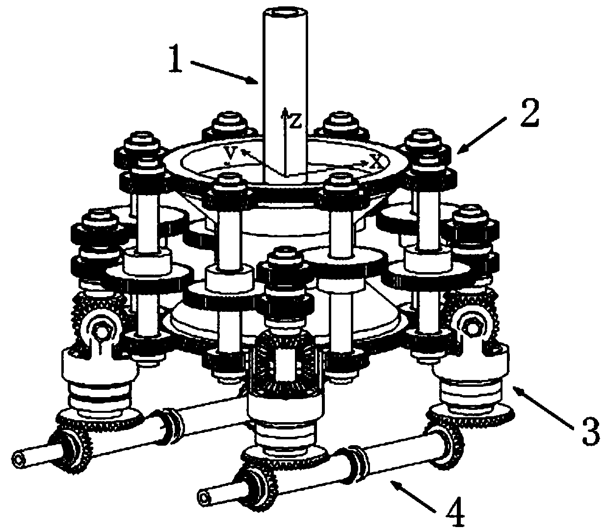
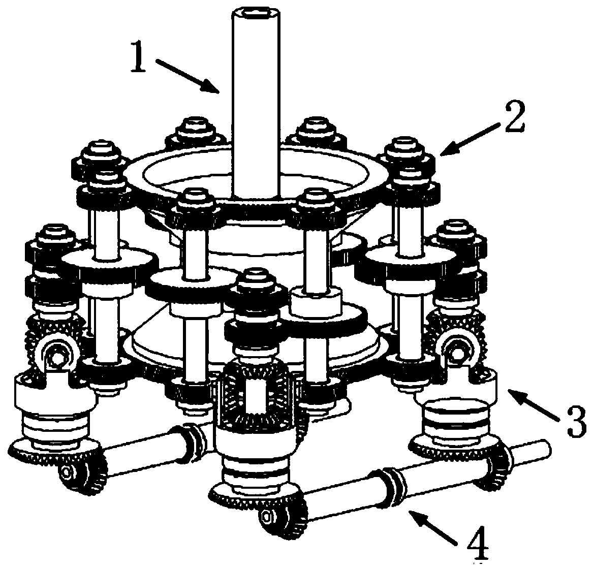
[0061] see figure 1 , figure 2 with Figure 7 , a split torque transmission reduction device for a helicopter, characterized in that it includes an output stage system 1, four secondary torque split systems 2, four primary torque split systems 3 and two input stage systems 4.

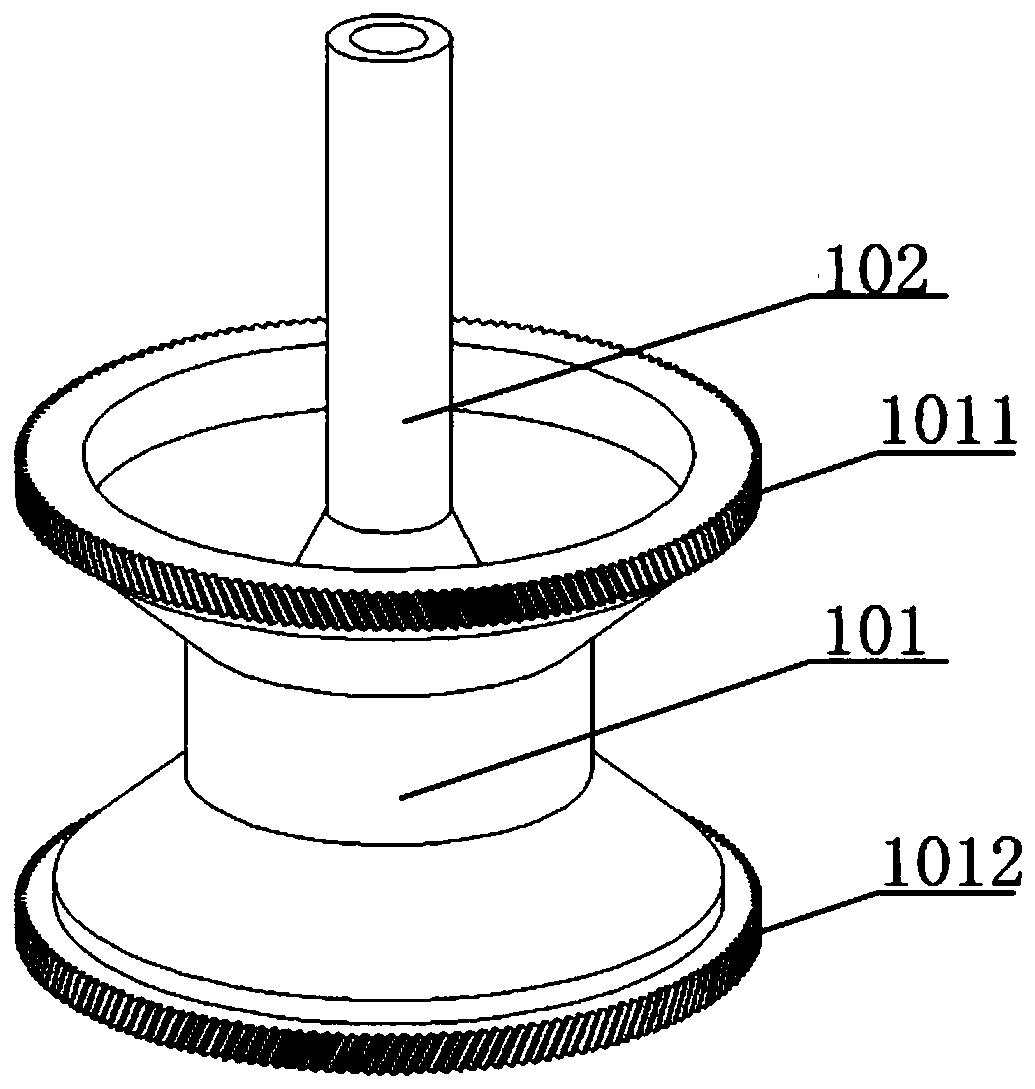
[0062] see image 3 , the output stage system 1 includes a herringbone gear 101 and an output shaft 102 .

[0063] The herringbone gear 101 is composed of an upper helical gear 1011 and a lower helical gear 1012 .

[0064] One end of the output shaft 102 is connected to the inner center of the herringbone gear 101 by a bolt. The other end of the output shaft 102 protrudes from the herringbone gear 101 in a direction closer to the upper helical gear 1011 . The herringbone gear 101 can drive the output shaft 102 to rotate.

[0065] A three-dimensional space coordinate system is established with the end face of the herringbone gear 101, wherein, the direction of the z axis is perpendicular to the en...

Embodiment 2

[0096] The main structure of this embodiment is the same as that of Embodiment 1. Furthermore, the center of the side wall of the spur gear I2011 has a boss I20111. The inside of the boss I20111 is a spline. The boss I20111 of the spur gear I2011 faces away from the direction of the z-axis, and is installed in the middle of the intermediate shaft I2012 through a spline.

[0097] The center of the side wall of the spur gear II2021 has a boss II20211. The interior of the boss II20211 is a spline. The boss II20211 of the spur gear II2021 faces the direction of the z-axis, and is installed in the middle of the intermediate shaft II2022 through a spline. That is, the spur gear I2011 and the spur gear II2021 are not on the same plane, so that the distance between the power transmission from the middle spur gear to the upper and lower helical gears in the two shaft systems is the same, thus satisfying the equalization of the two-stage torque distribution system 3 loading requireme...

Embodiment 3

[0099] The main structure of this embodiment is the same as that of Embodiment 1. Furthermore, the specifications and parameters of the spur gear I2011 of the first shaft system 201 and the spur gear II2021 of the second shaft system 202 are the same.

[0100] The specifications and parameters of the intermediate shaft I2012 of the first shaft system 201 and the intermediate shaft II2022 of the second shaft system 202 are the same.

[0101] The specifications and parameters of the helical gear I2013 of the first shaft system 201 and the helical gear III2023 of the second shaft system 202 are the same.

[0102] The specifications and parameters of the helical gear II 2014 of the first shaft system 201 and the helical gear IV 2024 of the second shaft system 202 are the same.


PUM


Abstract

The invention discloses a split torque transmission deceleration device for helicopters. The split torque transmission deceleration device for the helicopters is characterized by comprising an outputstage system, four two-stage split torque systems, four one-stage split torque systems and two input stage systems; the output stage system comprises a herringbone gear and an output shaft; each two-stage split torque system comprises a first shafting and a second shafting; each first shafting comprises a spur gear I, an intermediate shaft I, a helical gear I and a helical gear II; each second shafting comprises a spur gear II, an intermediate shaft II, a helical gear III and a helical gear IV; each first-stage split torque system comprises a bevel gear shaft, a supporting frame, a differential gear train, a spur gear III, an intermediate shaft III and a spur gear IV; and each input stage system comprises an input shaft, two intermediate shafts IV and two bevel gears. According to the split torque transmission deceleration device for the helicopters, a symmetrical arrangement structures and a differential shafting are adopted, so that all stages of split torque transmission are realized, the load-uniformizing requirement is met, and the service performance of a split torque transmission system is improved.

Description

technical field [0001] The invention relates to the field of helicopter transmission systems, in particular to a split-torque transmission reduction device for a helicopter. Background technique [0002] Since the helicopter came out, it has been widely used in military, transportation, rescue and other fields due to its advantages such as high maneuverability, convenient take-off and landing, and wide range of uses. [0003] Traditional helicopter reduction devices are mostly single-way transmission, which uses a combination of fixed-axis gear trains and planetary gear trains to decelerate step by step. This configuration is only suitable for light helicopters. With the continuous improvement of helicopter use requirements, the demand for heavy-duty helicopters continues to increase. However, due to the harsh service conditions of its parts, short service life, and prominent problems such as vibration and noise, traditional helicopter reduction gears are difficult to meet t...

Claims


Application Information

Patent Timeline
Patent Type & Authority Applications(China)
IPC IPC(8): F16H1/22
CPCF16H1/22
Inventor 林腾蛟杨金陈梦寒黄河陈兵奎
Owner CHONGQING UNIV
Why Eureka
Try Eureka