A split-torque transmission reduction device for a helicopter
A technology of split torque transmission and deceleration device, which is applied in the direction of transmission device, gear transmission device, mechanical equipment, etc., which can solve the problems of poor service conditions and short service life of parts and components, and achieve improved working performance, strong bearing capacity, and even load The effect of excellent performance
- Summary
- Abstract
- Description
- Claims
- Application Information
AI Technical Summary
Problems solved by technology
Method used
Image
Examples
Embodiment 1
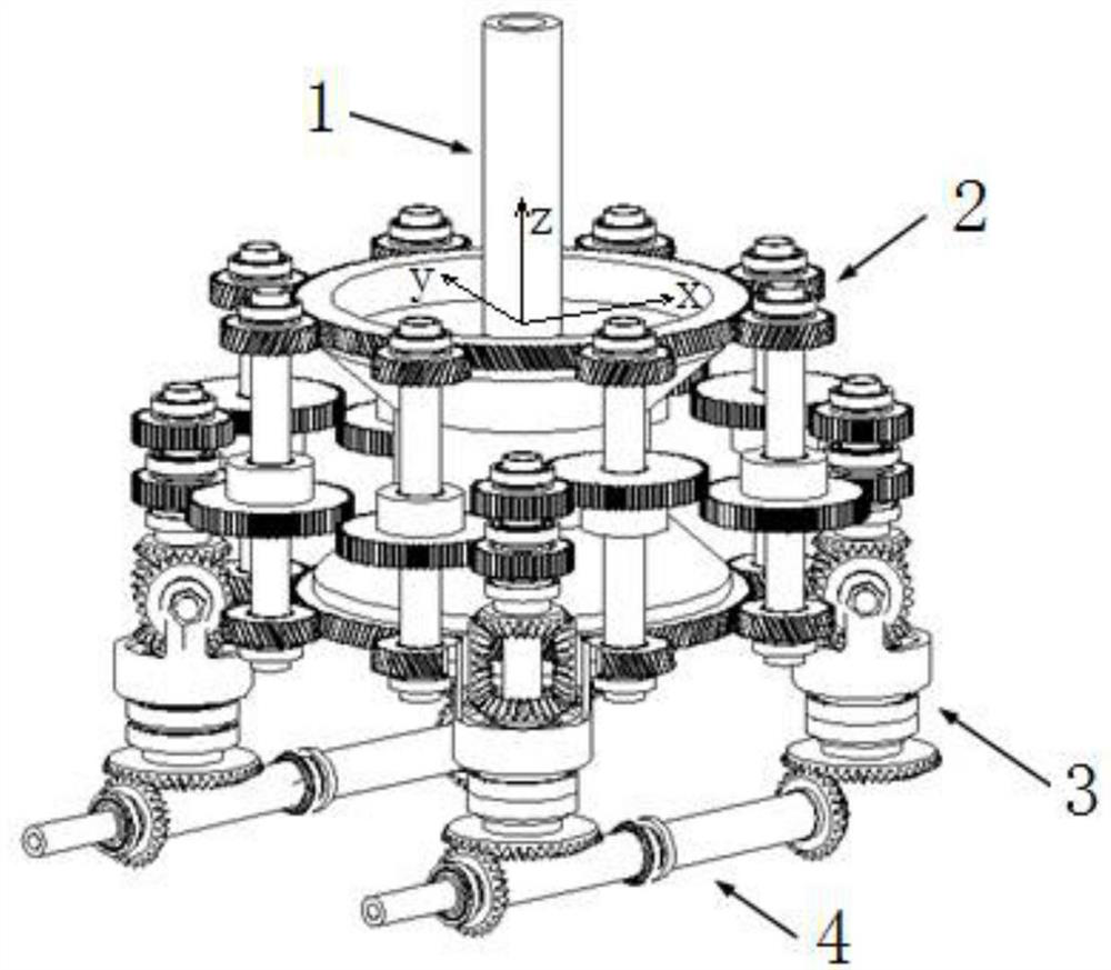
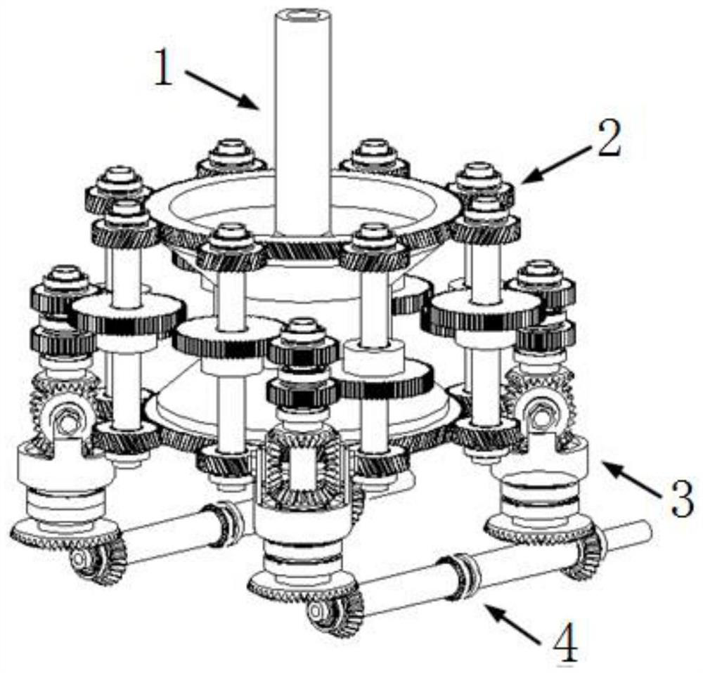
[0061] see figure 1 , figure 2 and Figure 7 , a split torque transmission reduction device for a helicopter, characterized in that it includes an output stage system 1, four secondary torque split systems 2, four primary torque split systems 3 and two input stage systems 4.
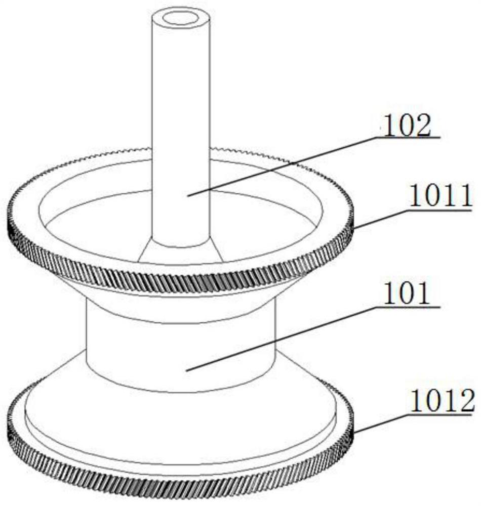
[0062] see image 3 , the output stage system 1 includes a herringbone gear 101 and an output shaft 102 .
[0063] The herringbone gear 101 is composed of an upper helical gear 1011 and a lower helical gear 1012 .
[0064] One end of the output shaft 102 is connected to the inner center of the herringbone gear 101 by a bolt. The other end of the output shaft 102 protrudes from the herringbone gear 101 in a direction closer to the upper helical gear 1011 . The herringbone gear 101 can drive the output shaft 102 to rotate.
[0065] A three-dimensional space coordinate system is established with the end face of the herringbone gear 101, wherein, the direction of the z axis is perpendicular to the end...
Embodiment 2
[0096] The main structure of this embodiment is the same as that of Embodiment 1. Furthermore, the center of the side wall of the spur gear I2011 has a boss I20111. The inside of the boss I20111 is a spline. The boss I20111 of the spur gear I2011 faces away from the direction of the z-axis, and is installed in the middle of the intermediate shaft I2012 through a spline.
[0097] The center of the side wall of the spur gear II2021 has a boss II20211. The interior of the boss II20211 is a spline. The boss II20211 of the spur gear II2021 faces the direction of the z-axis, and is installed in the middle of the intermediate shaft II2022 through a spline. That is, the spur gear I2011 and the spur gear II2021 are not on the same plane, so that the distance between the power transmission from the middle spur gear to the upper and lower helical gears in the two shaft systems is the same, thus satisfying the equalization of the two-stage torque distribution system 3 loading requireme...
Embodiment 3
[0099] The main structure of this embodiment is the same as that of Embodiment 1. Furthermore, the specifications and parameters of the spur gear I2011 of the first shaft system 201 and the spur gear II2021 of the second shaft system 202 are the same.
[0100] The specifications and parameters of the intermediate shaft I2012 of the first shaft system 201 and the intermediate shaft II2022 of the second shaft system 202 are the same.
[0101] The specifications and parameters of the helical gear I2013 of the first shaft system 201 and the helical gear III2023 of the second shaft system 202 are the same.
[0102] The specifications and parameters of the helical gear II 2014 of the first shaft system 201 and the helical gear IV 2024 of the second shaft system 202 are the same.
PUM
 Abstract
Description
Claims
Application Information
 - R&D
- Intellectual Property
- Life Sciences
- Materials
- Tech Scout
- Unparalleled Data Quality
- Higher Quality Content
- 60% Fewer Hallucinations
Browse by: Latest US Patents, China's latest patents, Technical Efficacy Thesaurus, Application Domain, Technology Topic, Popular Technical Reports.
© 2025 PatSnap. All rights reserved.Legal|Privacy policy|Modern Slavery Act Transparency Statement|Sitemap|About US| Contact US: help@patsnap.com


