[0026] In order to make it easy to understand the technical means, creative features, goals and effects achieved by the present invention, the present invention will be further explained in conjunction with specific implementations below.
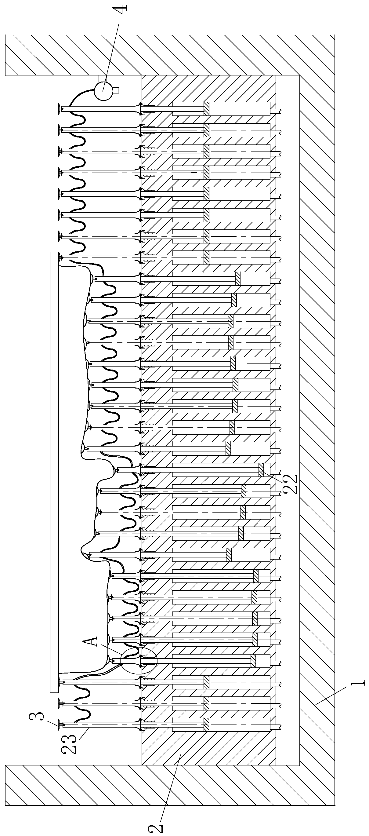
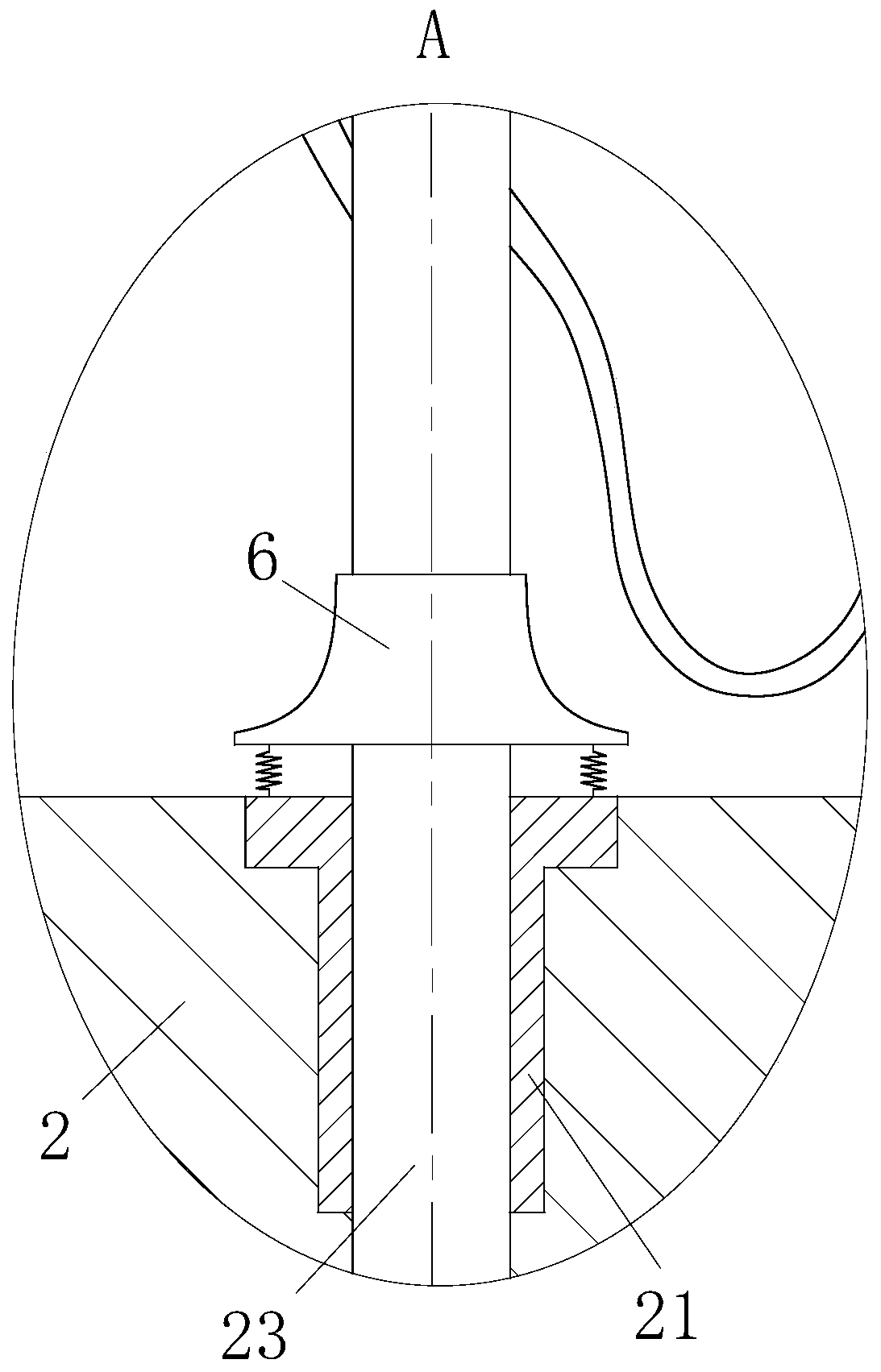
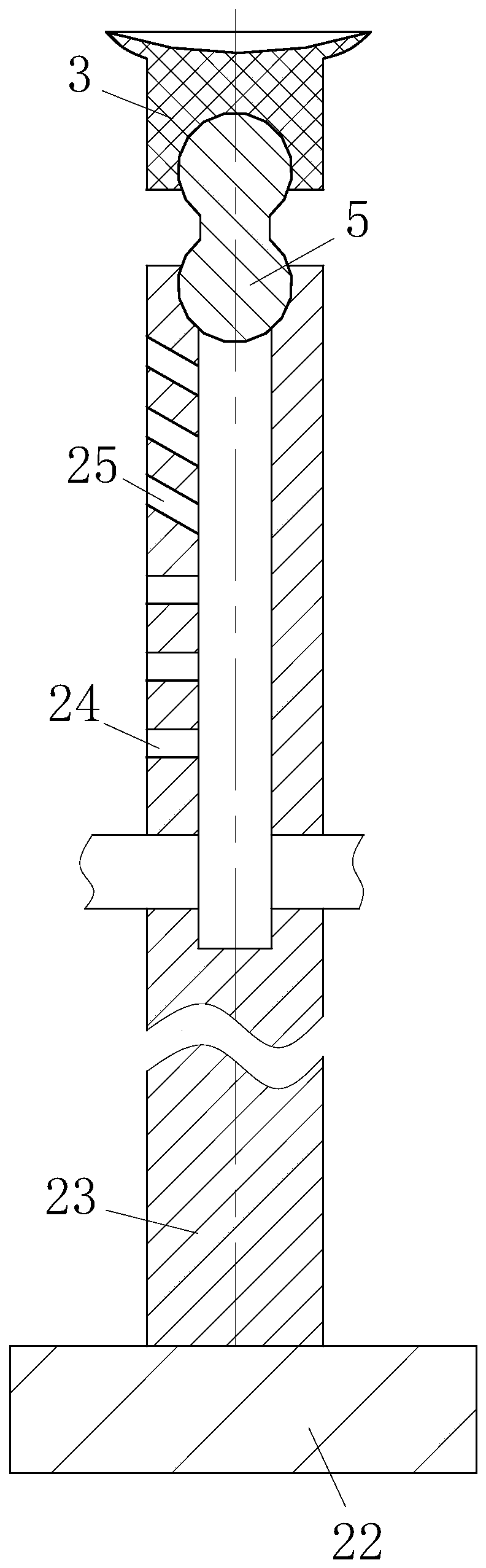
[0027] Such as Figure 1 to Figure 8 As shown, a welding fixture for high-end equipment manufacturing according to the present invention includes a fixed frame 1, a support plate 2 is arranged inside the fixed frame 1, and a cavity is uniformly provided on the support plate 2, and the cavity is provided with a support plate 2 A through hole connected above, a linear bearing 21 is installed in the through hole; the cavity is provided with a piston plate 22, and a piston rod 23 is provided on the piston plate 22. The upper end of the piston rod 23 passes through the through hole and the linear bearing 21 A suction cup 3 is also arranged inside; a trachea and a solenoid valve are connected to the lower end of the cavity; the support plate 2 is evenly divided into a plurality of regions.
[0028] When working, the workpiece to be welded is placed on the evenly distributed piston rod 23, and the solenoid valve of the control cavity is first opened, so that the piston rod 23 presses the piston rod 23 under the gravity of the workpiece, so that the workpiece is pushed by the piston rod 23. The upper end is supported. Then, according to the position of the welding seam on the workpiece to be welded, the lifting of the piston rod 23 in each area of the support plate 2 is adjusted to make the welding seam of the workpiece in a better welding position, which is completely closed at this time The solenoid valve connected to the internal cavity of the support plate 2, the piston rod 23 cannot move up and down, and the position of the workpiece cannot be moved. The linear bearing 21 makes the piston rod 23 unable to move left and right. When the workpiece squeezes the piston rod 23, the suction cup at the upper end of the piston rod 23 The gas in 3 is pressed out, the suction cup 3 absorbs the workpiece, and multiple suction cups 3 suck each position at the bottom of the workpiece, so that the workpiece is firmly fixed. At this time, the welder welds the weldment manually or mechanically The setting of multiple suction cups 3 fixes the weldment, so that the weldment can be firmly fixed, avoiding the influence of the deformation of the welding part on other parts of the weldment, so that the weldment after the welding can meet the geometric tolerance; There may be multiple welds on the workpiece. After one weld is welded, the position of the workpiece needs to be adjusted so that the other welds are in a better welding position. At this time, the solenoid valve is used to control the pistons in each area on the support plate 2 of the workpiece. The lifting of the rod 23 allows the position of the workpiece to be adjusted, avoiding the use of multiple fixtures for welding of a workpiece, resulting in waste of cost and affecting the efficiency of welding. At the same time, the lifting distance of the fixture through multiple piston rods 23 is different, making a variety of Workpieces of different shapes can be fixed and welded, which avoids manufacturing multiple fixtures, saves costs, and makes welding more convenient.
[0029] The upper end of the piston rod 23 is provided with a liquid storage tank, and the left side of the upper end of the piston rod 23 is provided with a horizontal through hole 24 and an inclined through hole 25 communicating with the liquid tank, and the inclined through hole 25 is located above the horizontal through hole 24 , The inclined through hole 25 is used to cool the weldment, and the horizontal through hole 24 is used to drive the water flow in the fixed frame 1; the right inner wall of the fixed frame 1 is provided with a circulating pump 4, which passes through the pipeline and A piston rod 23 that is approaching is connected, the circulating pump 4 is connected to the reservoir of the piston rod 23, and the reservoirs of the piston rod 23 are connected by pipelines. The circulating pump 4 is used to connect the The water is transported to the storage tank inside each piston rod 23. Due to the high temperature of the weldment during welding, the water on the support plate 2 in the fixed frame 1 has a cooling effect on the weldment, which avoids the poor welding effect caused by the excessively high welding temperature of the weldment; when the workpiece is placed, The piston rod 23 supporting the workpiece near the workpiece is controlled by the solenoid valve to retract to the bottom of the workpiece. At this time, the circulating pump 4 is turned on. The circulating pump 4 draws water from the fixed frame 1 and sends it to the reservoir of each piston rod 23 through the pipeline. After the water enters the liquid storage tank, part of the water flows out from the horizontal through hole 24 of the piston rod 23. The horizontal through holes 24 are all located on the left side so that the water flows evenly to the left, so that impurities, welding slag, etc. Washed to the left side of the support plate 2, impurities, welding slag, etc. are gathered together to facilitate subsequent cleaning. At the same time, the flow of water makes the temperature of the water in the fixed frame uniform, avoiding the temperature of the water when the water cools the weldment. The unevenness causes the local stress concentration at the welded joint of the weldment, which affects the welding quality of the weldment; another part of the water in the reservoir is directly sprayed to the bottom of the weldment through the inclined through hole 25, and the heat on the weldment Take it away and cool down the weldment to improve the quality of welding.
[0030] The upper end of the piston rod 23 is provided with a spherical groove, and the lower end of the suction cup 3 is provided with a spherical groove. The upper end of the piston rod 23 and the lower end of the suction cup 3 are connected by a connecting block 5 which is formed by combining two spherical blocks. When the workpiece squeezes the suction cup 3 and the piston rod 23 downward, the lower end of the suction cup 3 and the upper end of the piston rod 23 are connected by a connecting block 5 composed of two spherical blocks, so that the suction cup 3 can automatically adjust when the suction cup 3 contacts the weldment. Different angles are attached to the weldment, so that the suction cup 3 can fix different shapes of the weldment. The connecting block 5 composed of two spherical blocks makes the suction cup 3 rotate at a larger angle, which improves the suction cup 3 to have different shapes. Ability to absorb and fix the weldment.
[0031] The inner wall of the upper end of the reservoir of the piston rod 23 is chamfered around the circumference of the reservoir, the inner wall of the upper end of the piston rod 23 is provided with an annular groove 7, the inner wall of the annular groove 7 is provided with a ball 26, and the annular groove 7 is provided There is a rotating shaft 27, two ends of the rotating shaft 27 are in contact with the balls 26, and the rotating shaft 27 hinges the straight rod at the lower end of the suction cup 3 to each other. When the workpiece is placed on the upper end of the piston rod 23, the workpiece is in contact with the suction cup 3. The lower end of the straight rod of the suction cup 3 is hinged by the rotating shaft 27, so that the suction cup 3 can swing left and right in a single plane. The rotating shaft 27 is installed in the annular groove 7 to make the shaft 27 can rotate and enable the suction cup 3 to follow the rotation shaft 27. The chamfer at the upper end of the liquid storage tank increases the swing amplitude of the suction cup 3. The ball 26 in the annular groove 7 makes the rotation shaft 27 and the suction cup 3 more flexible and reduces The wear of the suction cup 3 is reduced, and the rotation and swing of the suction cup 3 enable the suction cup 3 to absorb the bottom of the workpiece in multiple directions, so that the suction cup 3 can fix a variety of workpieces with different shapes.
[0032] The straight rod of the suction cup 3 is provided with a plurality of diversion grooves 31, the diversion grooves 31 are evenly arranged around the axis of the suction cup 3, and the upper end of the diversion groove 31 is along the position of the suction cup 3 at the bottom of the suction cup 3. The bottom is inclined to both sides, and the diversion groove 31 is recessed inward at the bottom position of the suction cup 3; the gap between the lower end of the straight rod of the suction cup 3 and the inner wall of the liquid storage tank is 0.5-1mm, and the guide hole 25 is inclined The liquid area is 3.5-4mm 2. When water flows out from above the piston rod 23, the gap value between the lower end of the straight rod of the suction cup 3 and the inner wall of the reservoir is 0.5-1mm, and the liquid conduction area of the inclined through hole 25 is 3.5-4mm 2 , So that the lower end of the straight rod of the suction cup 3 has a strong blocking effect on water, so that most of the water flows out from the inclined through hole 25 at the upper end of the piston rod 23 to cool the bottom of the workpiece, ensuring that the temperature on the workpiece can be smoothly affected by the water Take away, the gap between the lower end of the straight rod of the suction cup 3 and the inner wall of the reservoir is 0.5-1mm, so that when part of the water flows out from the upper end of the piston rod 23, the speed of the water flow is relatively large, and the water flow impacts the straight rod of the suction cup 3 and The diversion groove 31 at the bottom of the suction cup 3 cools the suction cup 3, avoiding the excessive temperature on the suction cup 3, which may reduce or damage the service life of the suction cup 3. At the same time, the upper end of the diversion groove 31 is along the suction cup 3 at the bottom of the suction cup 3. The bottom is inclined to both sides, so that the water can be smoothly guided to both sides, reducing the direct impact of water on the bottom of the suction cup 3, avoiding the vibration of the workpiece by the suction cup 3, making the workpiece welding more stable and improving the quality of the workpiece welding , The diversion groove 31 is recessed inward at the bottom of the suction cup 3, so that the suction cup 3 is more easily squeezed and deformed by the workpiece, so that the suction cup 3 can smoothly suck the bottom of the workpiece, and the diversion groove 31 is at the bottom of the suction cup 3 The position is recessed inward, so that the ability of the suction cup 3 to bend and deform around at the recessed position is improved, so that the suction cup 3 can better adapt to the fixing of various workpieces of different shapes.
[0033] A rubber sleeve 6 is connected to the linear bearing 21 via a spring. The diameter of the rubber sleeve 6 gradually increases from top to bottom. The rubber sleeve 6 is hinged with a C-shaped extrusion block 61, two of the extrusion block 61 The end is provided with bristles 62 inclined upward, and the piston rod 23 first contacts the bristles 62 at the lower end of the pressing block 61 when the piston rod 23 moves downward. When the piston rod 23 moves downwards, because the bristles 62 of the extrusion block 61 incline upward, the piston rod 23 first contacts the bristles 62 at the lower end of the extrusion block 61 when it moves down, and the piston rod 23 drives the extrusion block 61 to rotate. Then the bristles 62 at both ends of the squeeze block 61 are in contact with the piston rod 23, the squeeze block 61 presses the piston rod 23, so that the rubber sleeve 6 and the piston rod 23 move downward together, and the rubber sleeve 6 squeezes the water below so that The impact of water drives the impurities and welding slag near the linear bearing 21 to move to both sides and agitate them to move in the water, avoiding the accumulation of welding slag and impurities at the linear bearing 21 and affecting the service life of the linear bearing 21 and the up and down of the piston rod 23 Movement; the bristles 62 tilt upwards so that the piston rod 23 receives little resistance when moving upwards, so that the piston rod 23 can move upwards smoothly.
[0034] The bristles 62 are made of rubber material, the bristles 62 are provided with cavities inside, the lower side of the bristles 62 are provided with liquid outlet holes 63, and the liquid outlet holes 63 are arranged obliquely upward. When the piston rod 23 moves downwards to contact the bristles 62, the bristles 62 are squeezed, and the water in the cavity in the bristles 62 flushes out the upper side of the other bristles 62, so that the impurities falling between the bristles 62 and the welding The slag can be washed away smoothly, preventing impurities from accumulating on the bristles 62 and scratching the piston rod 23. At the same time, a cavity is provided in the bristles 62, so that when the piston rod 23 moves downwards and just contacts the bristles 62, the water in the bristles 62 is squeezed. When the cavity is compressed, the water in the bristles 62 increases the rigidity of the bristles 62, so that the bristles 62 can smoothly compress the piston rod 23, so that the rubber sleeve 6 smoothly moves downward with the piston rod 23, and when the piston rod 23 moves upward At this time, because the water in the bristles 62 is squeezed out, the flexibility of the bristles 62 is good at this time, so that the piston rod 23 can smoothly move upward relative to the rubber sleeve 6.
[0035] The specific workflow is as follows:
[0036] When working, the workpiece to be welded is placed on the evenly distributed piston rod 23, and the solenoid valve of the control cavity is first opened, so that the piston rod 23 presses the piston rod 23 under the gravity of the workpiece, so that the workpiece is pushed by the piston rod 23. The upper end is supported. Then, according to the position of the welding seam on the workpiece to be welded, the lifting of the piston rod 23 in each area of the support plate 2 is adjusted to make the welding seam of the workpiece in a better welding position, which is completely closed at this time The solenoid valve connected to the internal cavity of the support plate 2, the piston rod 23 cannot move up and down, and the position of the workpiece cannot be moved. The linear bearing 21 makes the piston rod 23 unable to move left and right. When the workpiece squeezes the piston rod 23, the suction cup at the upper end of the piston rod 23 The gas in 3 is pressed out, the suction cup 3 absorbs the workpiece, and multiple suction cups 3 suck each position at the bottom of the workpiece, so that the workpiece is firmly fixed. At this time, the welder welds the weldment manually or mechanically The setting of multiple suction cups 3 fixes the weldment, so that the weldment can be firmly fixed, avoiding the influence of the deformation of the welding part on other parts of the weldment, so that the weldment after the welding can meet the geometric tolerance; There may be multiple welds on the workpiece. After one weld is welded, the position of the workpiece needs to be adjusted so that the other welds are in a better welding position. At this time, the solenoid valve is used to control the pistons in each area on the support plate 2 of the workpiece. The lifting of the rod 23 allows the position of the workpiece to be adjusted, avoiding the use of multiple fixtures for welding of a workpiece, resulting in waste of cost and affecting the efficiency of welding. At the same time, the lifting distance of the fixture through multiple piston rods 23 is different, making a variety of Workpieces of different shapes can be fixed and welded, which avoids manufacturing multiple fixtures, saves costs, and makes welding more convenient.
[0037] The above descriptions are only preferred embodiments of the present invention and are not used to limit the present invention. For those skilled in the art, the present invention may have various modifications and changes. Any modification, equivalent replacement, improvement, etc., made within the spirit and principle of the present invention shall be included in the protection scope of the present invention.