
Water floating system

A unit connection and array technology, applied in floating buildings, ship parts, anchoring arrangements, etc., can solve the problems of insufficient utilization of the site, high cost, insufficient use of anchoring devices, etc., to meet the needs of special use, improve Safety and stability, the effect of increasing the utilization of the site

Pending Publication Date: 2019-05-03
FUJIAN LYUHUA ENERGY INVESTMENT CO LTD
View PDF1 Cites 9 Cited by
  • Summary
  • Abstract
  • Description
  • Claims
  • Application Information

AI Technical Summary

Problems solved by technology

[0004] Although this anchoring method can solve the anchoring problem, it has the following defects: due to the mechanical characteristics of the anchor rope under tension but not compression, only one side of the anchor rope is in a tight state during the actual stress process, and the anchorage devices on the other three sides are under tension. It is not fully utilized; when the water level drops or rises, in order to avoid the drift of the floating system or the floating platform being pulled into the water, it takes a lot of manpower and material resources to adjust the length of the anchor rope; it is necessary to provide a larger site to accommodate the rest of the anchor rope. The phenomenon of rotation of the floating system caused by the large amount of water, resulting in insufficient utilization of the site; it cannot meet the needs of the floating system to rotate around a single point in some cases
[0005] Moreover, the unit connectors of the traditional floating system are made of plastic materials with high flexibility and poor mechanical properties. If the single-side anchoring method is used, when the floating unit transmits tension, the unit connectors are prone to tearing and damage due to tension; the floating unit transmits pressure. When the unit connector is prone to large deformation, it will cause the adjacent floating units to collide, which will cause the photovoltaic modules on the floating units to collide and be damaged.

Method used


Image

  • Water floating system
  • Water floating system
  • Water floating system

Examples


Embodiment 1

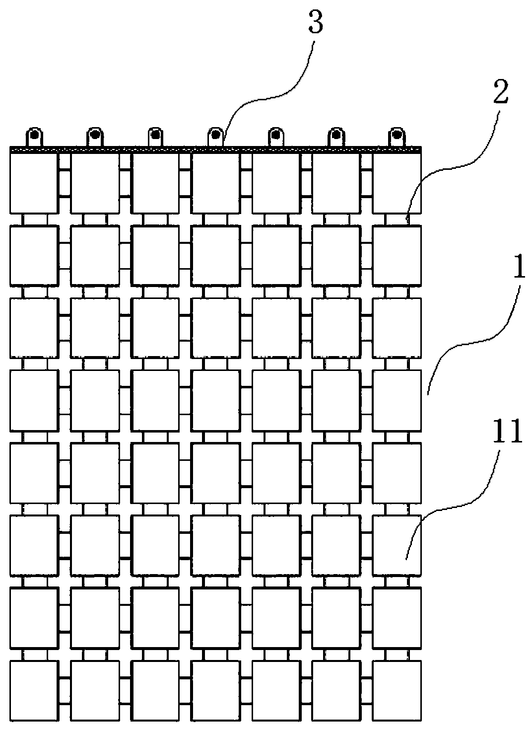
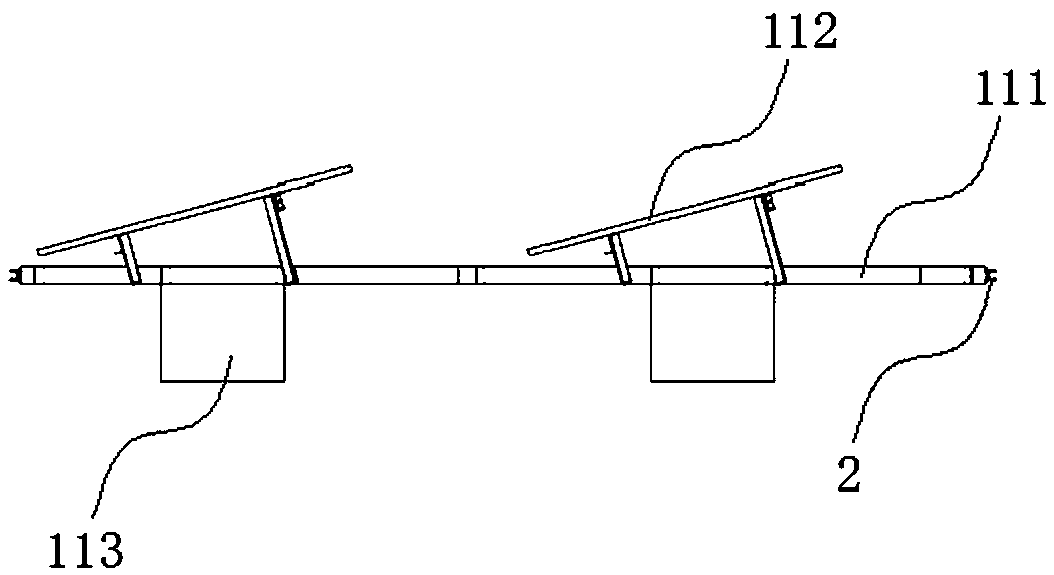
[0037] see figure 1 and figure 2 , a floating system on water, comprising a rectangular floating array 1, a connecting device 2 and an anchoring device 3, and a plurality of floating units 11 of the floating array 1 are arranged in a rectangular array. The floating unit 11 includes a rigid platform 111 of truss structure made of metal material arranged horizontally, several photovoltaic modules 112 are installed above the rigid platform 111 , and several floating blocks 113 are installed below the rigid platform 111 .

[0038] Two adjacent floating units 11 are connected by at least two connecting devices 2 arranged at intervals, and the connecting devices 2 are connected on the side of the rigid platform 111 of the floating units 11, preferably, between two adjacent floating units 11 The connecting device 2 between them is located on the same level as the rigid platform 111 of the floating unit 11. The connecting device 2 allows two adjacent floating units 11 to be displaced...

Embodiment 2

[0046] A water floating system includes a rectangular floating array 1, a connecting device 2 and an anchoring device 3, and a plurality of floating units 11 of the floating array 1 are arranged in a rectangular array. The structures of the floating unit 11 and the anchoring device 3 in the second embodiment are the same as those of the floating unit 11 in the first embodiment.

[0047] Two adjacent floating units 11 are connected by at least two connecting devices 2 arranged at intervals. The connecting device 2 is connected to the side of the rigid platform 111 of the floating unit 11. The connecting device 2 allows two adjacent floating units 11 to The relative displacement in the horizontal direction and the vertical direction can occur without colliding with each other, and the deflection angle of two adjacent floating units 11 in the vertical direction is limited.

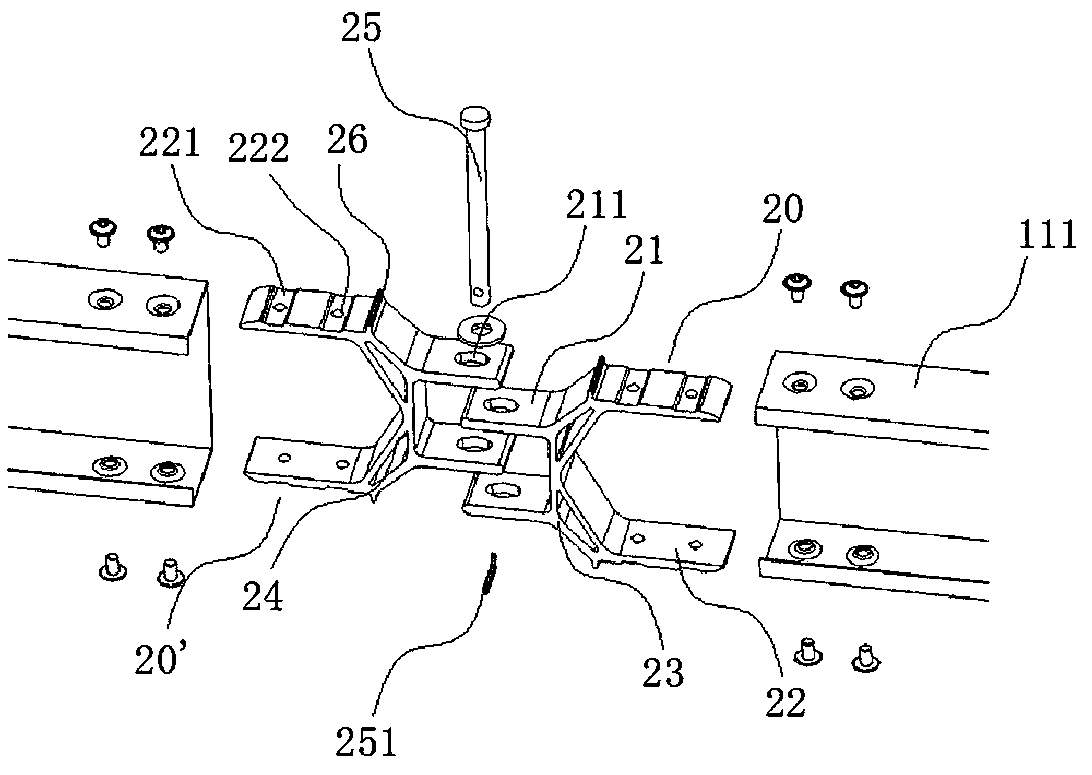
[0048] Specifically, see Figure 8 and Figure 9 , The connection device 2 includes a first unit connect...

Embodiment 3

[0054] see Figure 10 , a floating system on water, comprising an anchoring device 3 and a floating array 1 distributed on the outer periphery of the anchoring device 3 , a plurality of floating units 11 of the floating array 1 are radially distributed on the outer periphery of the anchoring device 3 , between two adjacent floating units 11 They are connected by at least two connecting devices 2 arranged at intervals, and the connecting devices 2 are connected to the floating unit 11 . The anchoring device 3 in the third embodiment is basically the same in structure as the anchoring device 3 in the second embodiment, except that the main hoop 32 is connected to the adapter assembly 31 through several connecting rods.

[0055] The structure of the floating unit 11 in the third embodiment is the same as that of the floating unit 11 in the first embodiment. The connecting device 2 in the third embodiment may have the same structure as the connecting device 2 in the first or seco...


PUM


Abstract

The invention relates to a water floating system which comprises a floating array; the floating array comprises a plurality of floating units; every two adjacent floating units are connected through at least two connecting devices arranged at intervals, and the connecting devices are connected to the side edges of a rigid platform; the floating array is anchored on the bank side or the water bottom only through an anchoring device located on one side of the floating array or an anchoring device located in the center of the floating array; the connecting devices allow the two adjacent floatingunits to generate relative displacement in the horizontal direction and the vertical direction and not to collide with each other, and limit the deflection angles of the two adjacent floating units inthe vertical direction. According to the system, the system cost is greatly reduced in a single-side or central anchoring mode, collision between the adjacent floating units is effectively prevented,and therefore photovoltaic modules on the floating units are protected.

Description

technical field [0001] The invention relates to the technical field of photovoltaic power generation, in particular to a floating system on water. Background technique [0002] Under the action of wind and waves, the existing water floating systems tend to move away from each other or approach each other. They need to be connected through connecting devices to transmit the internal force of the wind and waves in the floating array, and finally transmit the internal force to the anchoring device. The existing floating on water The system adopts the anchoring method of anchoring around. [0003] The method of anchoring around the floating system is to arrange anchor points around the floating system, and then connect the anchor points on the floating system with the sinking anchors and piles distributed around the floating system through anchor ropes, and then play the role of fixing the floating system , For example, the anchoring method disclosed in the Chinese invention pa...

Claims


Application Information

Patent Timeline
Patent Type & Authority Applications(China)
IPC IPC(8): B63B35/44B63B21/50
Inventor 郭其秀兰品光
Owner FUJIAN LYUHUA ENERGY INVESTMENT CO LTD
Learn More