High temperature and high pressure resistant compensator

A high-voltage compensation and high-temperature-resistant technology, which is applied in the field of compensators, can solve problems such as safety concerns, reduced maintenance workload, and bellows rupture and failure, and achieve high reliability, long service life, and overcome aging and regular maintenance problems. Effect

Active Publication Date: 2019-05-03
LUOYANG SUNRUI SPECIAL EQUIP
View PDF9 Cites 6 Cited by
  • Summary
  • Abstract
  • Description
  • Claims
  • Application Information

AI Technical Summary

Problems solved by technology

Years of use have shown that the sealing performance of the second-generation sleeve compensator has improved to a certain extent, and the maintenance workload has been reduced to a certain extent, but there are still problems that require frequent maintenance.
The third generation adopts the sealing structure combining packing and sealing ring, and the sealing effect of the compensator is improved. However, because the existing sealing ring is not resistant to high temperature, the overall structure is mainly based on packing. The important application field of the sleeve compensator has always been urban Hot water pipes for heating cannot be applied to high temperature pipes above 350°C
[0003] The existing technology of high-temperature pipelines mostly uses metal bellows expansion joints to compensate for the thermal expansion of the pipeline. Since the metal bellows is a thin-walled structure, it is more sensitive to the working conditions of use, and the bellows is prone to rupture and failure, causing people to worry about safety.

Method used


Image

  • High temperature and high pressure resistant compensator
  • High temperature and high pressure resistant compensator

Examples


Embodiment Construction

[0012] The present invention is described with reference to the drawings and specific embodiments, but the present invention is not limited to these embodiments.

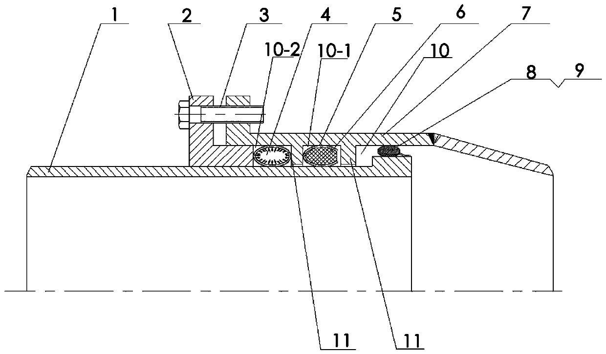
[0013] Such as figure 1 As shown, a high temperature and high pressure compensator includes an outer tube 7 sleeved on the outside of the core tube 1, an annular channel 10 is provided between the outer tube 7 and the core tube 1, and the outer tube 7 and the core tube 1 can slide relatively. The compensator also includes a gland 2, a retaining ring 11, an annular boss 12, a fixing piece, an inflatable metal O-shaped sealing ring 4, a C-shaped metal sealing ring 5 filled with ceramic fibers 6, and a wire mesh dustproof sealing ring 8. The gland 2 is sleeved on the outside of the core tube 1 and fixed on the end of the outer tube 7 by a fixing piece. One end of the gland 2 extends into the annular channel 10. The fixing piece can be in the form of welding or pressing bolts. When using compression bolts for connectio...


PUM


Abstract

The invention relates to a high temperature and high pressure resistant compensator. The high temperature and high pressure resistant compensator comprises an outer pipe arranged at the outer side ofa core pipe in a sleeving manner, wherein an annular passage is arranged between the outer tube and the core tube. The compensator further comprises a gland, a baffle ring, a ring-shaped boss, a fixedpart, an inflation type O-shaped metal seal ring, a C-shaped metal seal ring filled with ceramic fibers and a wire mesh dustproof seal ring. According to the movement characteristics and working conditions of a pipeline-based axial compensator, firstly the high-temperature resistant inflation type O-shaped metal seal ring and the C-shaped metal seal ring filled with the ceramic fibers are combined to seal the structure, and then the dustproof structure is used for protecting a sealing interface, so that the traditional packing seal and nonmetal sealing ring combined sealing is replaced, and the difficult problem that a traditional compensator ages and needs to be maintained at fixed periods is solved; and the high temperature and high pressure resistant compensator has long service life and high reliability.

Description

technical field [0001] The invention relates to a compensator, in particular to a high temperature and high pressure resistant compensator. Background technique [0002] The purpose of pipeline compensation is to reduce pipeline temperature stress and ensure pipeline safety. Compensators for pipeline compensation mainly include sleeve compensators and metal bellows expansion joints, among which sleeve compensators are the most traditional pipeline compensators. Sleeve compensators are generally sealed with stuffing. One end tube is designed with a stuffing box, and the other side is a core tube. The stuffing is compacted in the stuffing box through the gland. During operation, the core tube slides in the stuffing box to realize compensation. The first-generation sleeve-type compensator with packing as sealing material leaks due to the wear of the sealing layer during use, which has the fatal disadvantage of having to stop using and replace the packing, which adds a lot of ...

Claims


Application Information

Patent Timeline
Patent Type & Authority Applications(China)
IPC IPC(8): F16L51/00F16J15/06F16J15/10
Inventor 李德雨佘东升张爱琴
Owner LUOYANG SUNRUI SPECIAL EQUIP
Why Eureka
Try Eureka