A method and system for monitoring rotor blades of a turbomachine using blade tip timing (BTT)

A technology of rotor blades and turbines, applied in gas turbine engine testing, using electromagnetic means, using wave/particle radiation, etc., can solve problems such as expensive and uncommon

Active Publication Date: 2019-05-03
UNIVERSITY OF PRETORIA
View PDF17 Cites 4 Cited by
  • Summary
  • Abstract
  • Description
  • Claims
  • Application Information

AI Technical Summary

Problems solved by technology

While such data acquisition systems are available, they are not common and can be prohibitively expensive

Method used


Image

  • A method and system for monitoring rotor blades of a turbomachine using blade tip timing (BTT)
  • A method and system for monitoring rotor blades of a turbomachine using blade tip timing (BTT)
  • A method and system for monitoring rotor blades of a turbomachine using blade tip timing (BTT)

Examples


Embodiment Construction

[0074] The following description of the invention is intended only as a practical teaching of the invention. It will be apparent to those skilled in the art that many changes can be made to the described embodiments while still obtaining the beneficial results of the invention. It is also apparent that some of the intended benefits of the invention can still be achieved by selecting some of the features of the invention without changing others. Accordingly, those skilled in the art will recognize that modifications and adaptations to the present invention exist (and in some cases can even be desirable) and are a part of the present invention. Accordingly, the following description is provided to illustrate the principles of the invention and not to limit it.

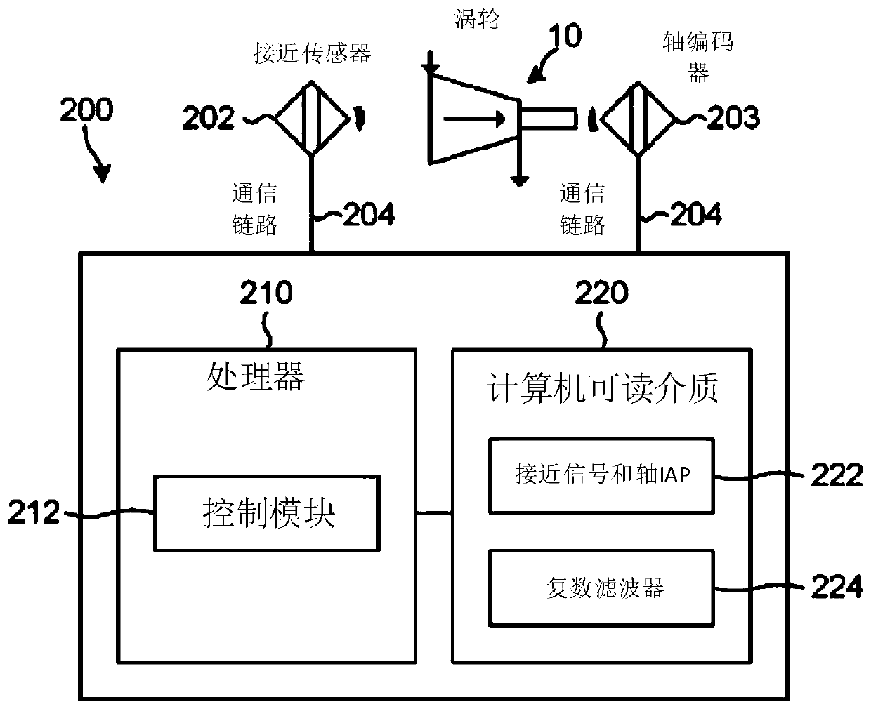
[0075] figure 2 Illustrated is a system 200 configured to determine or estimate tip deflection characteristics of moving rotor blades in a turbomachine. In this example, the turbine is turbine 10 . Turbine 10 may be...


PUM


Abstract

A method (400) of determining blade tip deflection characteristics is applied to moving rotor blades (R1, R2) in a turbomachine (10) comprising a housing and rotor including a shaft with the rotor blades attached thereto and at least one proximity probe (202). The method (400) includes measuring ((402) a proximity signal caused by a presence of a proximate tip of a moving rotor blade (R1) and calculating (404) by a control module (212) a shaft Instantaneous Angular Position (IAP) as a function of time, and performing (410) an order tracking process which includes expressing (412) the measuredproximity signal in the angular domain and resampling (414) the expressed proximity signal to render it equidistant in the angular domain. The method (400) includes performing (416) a pulse localisation process which includes filtering (418) the proximity signal yielding a complex-valued response, expressing (420) the complex-valued response in terms of a local amplitude and phase, and calculating(422) local phase shifts between each expressed signal and a reference signal.

Description

technical field [0001] The present invention relates to monitoring of turbomachines, and more particularly, to methods and systems for monitoring turbine rotor blades using blade tip timing (BTT). Background technique [0002] Turbines can be classified as machines that extract work from or perform work on a fluid (such as any liquid or gas) by rotating blades. Blades (hereinafter referred to as rotor blades) are connected to a rotating shaft (hereinafter referred to as rotor). Therefore, the rotor blades are fundamental to the operation of any turbine. [0003] Since rotor blades are mechanical structures, the entire structure vibrates when excited (ie, when a dynamic load is applied to the structure, such as when the rotor blade acquires energy from or imparts energy to a fluid). The tip deflection of the rotor at each instant is defined as the displacement distance of the tip from its non-vibrating state (ie rest state). Thus, tip deflection is the change in position o...

Claims


Application Information

Patent Timeline
IPC IPC(8): G01H1/00G01H11/00
CPCG01H1/006G01H11/00F05D2260/80F05D2260/81G01H9/00G01M15/14
Inventor 大卫·赫拉克勒斯·戴蒙德菲利普斯·斯特凡努斯·海恩斯亚伯拉罕·约翰尼斯·奥贝霍尔斯特
Owner UNIVERSITY OF PRETORIA
Why Eureka
Try Eureka