Clamp for long shaft type irregular outer circle workpieces

An irregular, long-axis technology, applied in the direction of manufacturing tools, metal processing machinery parts, metal processing equipment, etc., can solve problems such as positioning and clamping difficulties, achieve high work efficiency, reduce production costs, and use simple effects

Pending Publication Date: 2019-05-07
新乡市豫北靖道汽车零部件有限公司
View PDF6 Cites 0 Cited by
  • Summary
  • Abstract
  • Description
  • Claims
  • Application Information

AI Technical Summary

Problems solved by technology

[0003] Aiming at the defects and problems of existing fixtures, the present invention provides a long-axis irregular outer-circular workpiece fixture, which solves the problem of difficult positioning and clamping of existing equipment when processing irregular outer-circular workpieces

Method used


Image

  • Clamp for long shaft type irregular outer circle workpieces
  • Clamp for long shaft type irregular outer circle workpieces
  • Clamp for long shaft type irregular outer circle workpieces

Examples


Embodiment 1

[0018] Embodiment 1: as figure 1 The long-axis irregular outer circle workpiece fixture shown in the figure is to provide a fixture that can hold irregular outer circle workpieces, from figure 1 It can be seen that a center frame 1 is provided directly in front of the lathe spindle 6 in the running direction, and a plurality of radially distributed rollers are arranged on the center frame 1. These rollers are combined to form a ring-shaped installation channel, and a positioning and locking device can be set in the installation channel. , the positioning and locking device includes a disc body 2, claws 3 and coil wire 4, from figure 2 It can be seen that the outer peripheral surface of the front side of the disc body 2 is set in the annular channel formed by the combination of the rollers of the center frame 1. The disc body 2 is a hollow annular body, and a through hole for fitting the workpiece 5 is opened along the axial direction of the disc body. 2 There is a ring groov...

Embodiment 2

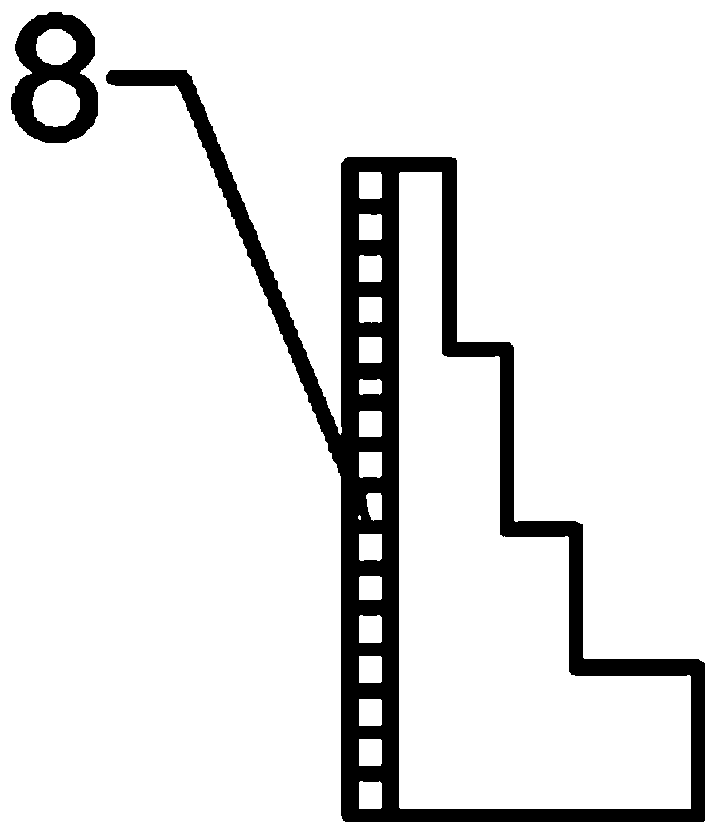
[0021] Embodiment 2: This embodiment 2 is basically the same as embodiment 1. In order to ensure the locking effect of the claw 3, the difference is that, as Figure 7 As shown, the bottom surface of the claw 3 is tooth-shaped, and the claw 3 presses the workpiece 5 inwardly along the radial direction of the disc body 2 and locks it. Yes, when the pressure is constant, reducing the force-bearing area can increase the pressure and increase the friction between the claw 3 and the workpiece 5, and the workpiece 5 is screwed by the coil wire 4, the coil wire 4, the claw 3 and the disc After the body 2 clamps the workpiece 5, it rotates together with the workpiece 5 in the center frame to prevent the irregular outer circular workpiece 5 from turning over in the disc body 2, so that the jaws 3 have a better clamping effect.

[0022] Further, such as Figure 7 As shown, the top is provided with an end cover, which prevents the claw 3 from falling into the disc body 2, and is conveni...

Embodiment 3

[0023] Embodiment 3: Embodiment 3 is based on Embodiment 1 or Embodiment 2, in order to ensure the locking effect, such as Figure 6 As shown, teeth 10 are provided on the outer periphery of the rear side of the coil wire 4, and positioning holes 11 are provided on the disc body 2. Insert the rotating shaft of 12 into the positioning hole 11, use the teeth 10 on the wrench 12 to mesh with the teeth 10 on the wire 4, turn the wrench 12 counterclockwise, the teeth 10 on the wrench 12 rotate to drive the teeth on the wire 4 10 Turn clockwise, so that the pushing claw 3 of the deep groove thread on the coil 4 presses the workpiece 5 inwardly along the radial direction of the disc body 2 and locks it

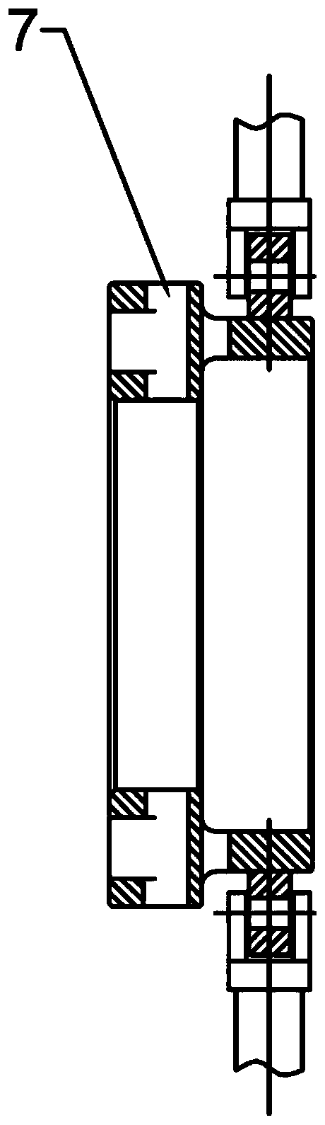
[0024] It can be seen that the structure of the present invention is novel and unique. A disc body 2 is arranged on the existing center frame 1, and a plurality of claw through holes 7 are set on the disc body 2, and the claws 3 are set in the claw through holes 7. The movable claw ...


PUM


Abstract

The invention discloses a clamp for long shaft type irregular outer circle workpieces. The clamp comprises a center frame and a locating and locking device. The locating and locking device comprises adisc body, clamping claws and a disc wire. A through hole is formed in the center of the disc body and used for sleeving a workpiece. The outer circumference face of the front side of the disc body is mounted on rolling wheels of the center frame in a sleeving manner. A ring groove is formed in the end face of the rear side of the disc body. The front side of the disc wire can be sleeved in the ring groove. A thread is formed on the annular face of the front side of the disc wire. Multiple T-shaped clamping claw through holes are formed in the peripheral side of the rear side of the disc bodyin the radial direction of the disc body. The clamping claw through holes penetrate through the ring groove. The clamping jaws are in T shapes matched with the clamping claw through holes, and the left portion of each T shape is larger than the right portion. The end faces of the rear sides of the clamping claws are in thread shapes. The clamping claws are assembled in the clamping claw through holes and can move in the radial direction of the disc body. The structure is novel and unique, manpower and money input are saved, the production cost is reduced, and the problem that locating and clamping are difficult when existing quipment machines irregular outer circle workpieces is solved effectively, the work efficiency is high, and the application range is wide.

Description

technical field [0001] The invention relates to a fixture, in particular to a long-axis irregular outer circle workpiece fixture. Background technique [0002] In the machinery manufacturing industry, lathes, especially CNC lathes, are widely used. However, in actual processing, there are many cylindrical workpieces with cast surfaces and irregular shapes. Such workpieces do not have good auxiliary fixtures during processing, and often It is difficult to unload and unload during processing, and the clamping effect is poor. In the traditional process, the processing of long-axis workpieces requires a steady rest. The steady rest can only clamp regular workpieces with outer circles, and workpieces with irregular outer circles need to be aligned after machining the outer circles. It is time-consuming and labor-intensive to use the center frame to process, and it is impossible to mass-produce irregular outer-circular workpieces, especially some heterogeneous workpieces. At this ...

Claims


Application Information

Patent Timeline
Patent Type & Authority Applications(China)
IPC IPC(8): B23Q1/76
Inventor 王营彬甄晓光崔星珂
Owner 新乡市豫北靖道汽车零部件有限公司
Why Eureka
Try Eureka