A Method of Accurately Calibrating Robot Endpoint and Vision System

A vision system and robot technology, which is applied in the field of precise calibration of the robot end and the vision system, can solve the problems that the calibration method cannot achieve three-dimensional coordinate transformation, the one-dimensional information is difficult to deal with complex calculations, and cannot achieve accurate calibration, etc., so as to improve the overall Operational efficiency, good application results, easy-to-achieve results

Active Publication Date: 2021-07-23
NANJING ESTUN ROBOTICS CO LTD
View PDF0 Cites 0 Cited by
  • Summary
  • Abstract
  • Description
  • Claims
  • Application Information

AI Technical Summary

Problems solved by technology

[0004] The technical problem solved by this patent is that the point laser can only obtain the distance information of the measured place due to its measurement principle, and the one-dimensional information is difficult to cope with complex calculations, which has great limitations. The calibration method under the point laser cannot realize the three-dimensional coordinates Conversion, technical problems that cannot achieve accurate calibration

Method used


Image

  • A Method of Accurately Calibrating Robot Endpoint and Vision System
  • A Method of Accurately Calibrating Robot Endpoint and Vision System
  • A Method of Accurately Calibrating Robot Endpoint and Vision System

Examples


Embodiment

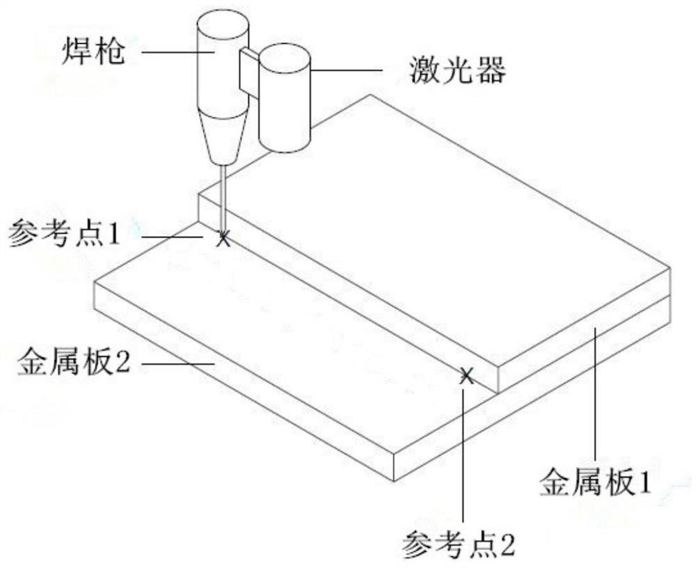
[0094] According to the method of accurately calibrating the end of the robot and the vision system, do an experiment on reference point 1, and the following data can be obtained:

[0095] for for for for for for for for for for

[0096] Set the matrix to be solved for

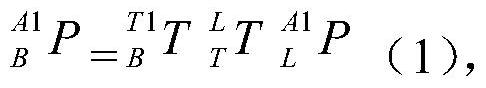
[0097] the above for for for and the solved matrix for At the same time into the formula (3) Among them, the formula (1) is obtained;

[0098]

[0099] the above for for for and the solved matrix for At the same time into the formula (5) Among them, the formula (2) is obtained;

[0100]

[0101] the above for for for and the solved matrix for At the same time into the formula (7) Among them, the formula (2) is obtained;

[0102]

[0103] Formulas (1)(2)(3) can be arranged to get formulas (4)(5)(6), as follows:

[0104]

[0105]

[0106]

[0107] Formula (7)(8)(9) can be obtained by rearranging formula (4)(5)(6):

[0108...


PUM


Abstract

The invention discloses a method for accurately calibrating a robot end and a vision system; a. select two reference points, b. obtain the coordinates of the two reference points in the base coordinate system; c. adjust the position of the industrial robot in step d, and record The coordinates of the two reference points in the laser coordinate system in the laser; record the coordinates of the two reference points in the base coordinate system; e, transform the posture of the industrial robot, and record the coordinates of the two reference points in the laser coordinate system in the laser ; Record the coordinates of the two reference points in the base coordinate system; f, transform the posture of the industrial robot, record the coordinates of the two reference points in the laser coordinate system in the laser; record the coordinates of the two reference points in the base coordinate system. Advantages: This method can obtain the relative relationship between the laser vision coordinate system and the robot coordinate system, realize the conversion of the coordinates of the measured object in the laser vision to the coordinates of the robot, improve the overall operating efficiency of the system, and have good application effects.

Description

technical field [0001] The invention relates to a method for accurately calibrating a robot terminal and a vision system. Background technique [0002] Laser sensor is a sensor that uses laser technology for measurement. As a new type of measuring instrument, it can realize non-contact long-distance measurement, and has the advantages of fast speed, high precision, large measuring range and strong anti-interference ability. [0003] Laser sensors are further divided into point lasers and line lasers, and point lasers can only obtain distance information of the measured place due to their measurement principles, and one-dimensional information is difficult to cope with complex calculations, which has great limitations. The calibration method under the point laser cannot realize the conversion of three-dimensional coordinates, and cannot achieve accurate calibration. Therefore, finding a calibration method that can obtain the positional relationship between the laser vision a...

Claims


Application Information

Patent Timeline
Patent Type & Authority Patents(China)
IPC IPC(8): B25J9/16B25J19/00
CPCB25J9/16B25J19/00
Inventor 鞠青辰宋方方王杰高
Owner NANJING ESTUN ROBOTICS CO LTD
Why Eureka
Try Eureka