Hydraulic support frame

A technology of hydraulic support and support controller, which is applied in mine roof support, mining equipment, earthwork drilling and mining, etc., which can solve the problems of affecting the stability of support support, not being well adapted, and the forward tilt of the top beam, so as to increase the Coal control effect, adaptation to the roof environment, and the effect of avoiding the forward tilt of the support

Inactive Publication Date: 2019-05-07
BIN COUNTY WATER CURTAIN CAVE COAL
View PDF0 Cites 2 Cited by
  • Summary
  • Abstract
  • Description
  • Claims
  • Application Information

AI Technical Summary

Problems solved by technology

[0002] At present, the geological conditions of coal mines are complex and various hydraulic supports are required. For example, Changcun Coal Mine has moderate geological conditions, a mining depth of about 980m, and high pressure. ZF5500 / 18 / 28, ZF6400 / 17.5 / 28, and ZF7000 / 18 / 28 hydraulic supports have been used successively , to a certain extent, cannot meet the requirements of use, because the existing ZF5500 / 18 / 28, ZF6400 / 17.5 / 28, ZF7000 / 18 / 28 hydraulic supports all have the phenomenon of low pressure when the mining depth is about 980m
At the same time, the sensor of the plug-in jack of the top-coal caving hydraulic support adopts a proximity switch, which can only detect the expansion and contraction of the plug-in board, but cannot detect and control the extension length of the plug-in board, that is, the size of the coal discharge port cannot be adjusted, so it cannot be well adapted to different situations. The requirements of the coal seam for the top-coal caving process; during the coal caving process, there is a problem of the roof beam leaning forward, and the roof beam has no tilt sensor, which cannot ensure the horizontal state of the support top beam, which affects the stability of the support support

Method used


Image

  • Hydraulic support frame
  • Hydraulic support frame
  • Hydraulic support frame

Examples


Embodiment 1

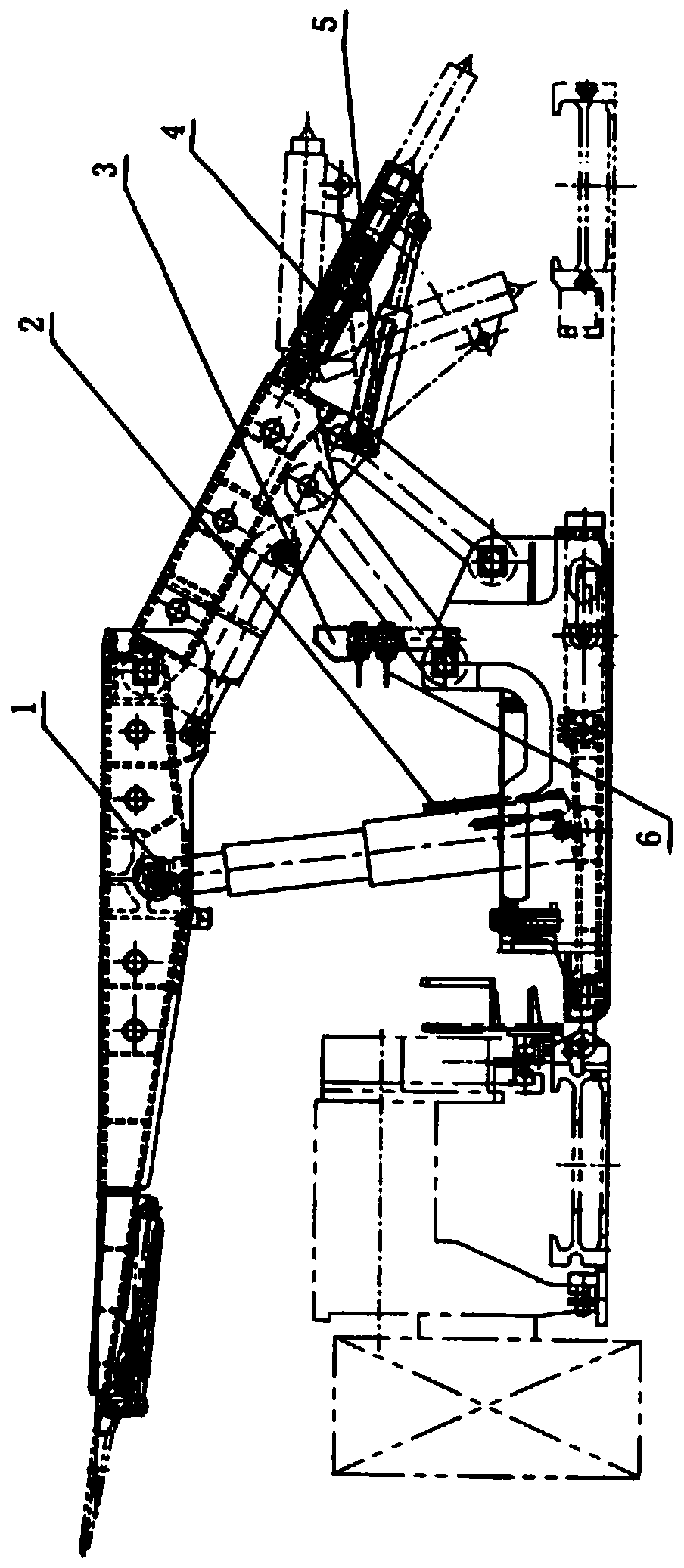
[0034] Example 1: In figure 1 , 2 It shows that the bracket of the present invention is composed of a bracket body and an electro-hydraulic control system.

[0035] The support body is a two-column cover-type low-level coal caving hydraulic support, which consists of a top beam, a column, a base, a cover beam, a balance jack, a front connecting stalk, a rear connecting stalk, side guards and side guard jacks, side guards and side guards. Guard plate pushing jack, front conveyor pushing jack, rear conveyor pulling jack, base lifting jack, and tail beam of coal discharge mechanism, tail beam jack, inserting plate and inserting plate jack, etc.

[0036] A tilt sensor 1 is installed on the top beam of the bracket and in front of the column, a pressure sensor 2 is installed on the valve plate of the hydraulic cylinder lower chamber of the column, an electro-hydraulic valve group 6 is installed on the operating frame of the base, and the bracket controller 3 is installed on the Ab...

Embodiment 2

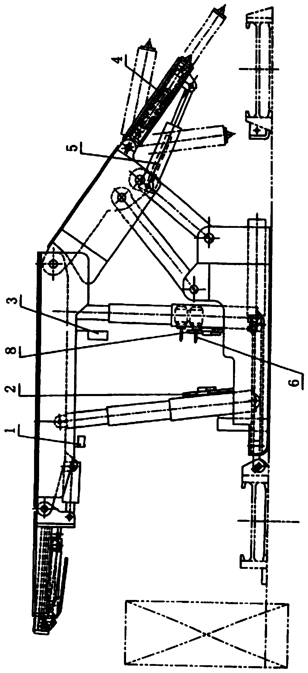
[0051] Example 2: image 3 Another form of the hydraulic support of the present invention is shown: an electro-hydraulic control four-column support shield type low-position top coal caving hydraulic support. Its upright column is four, divides front, rear two rows, does not need balance jack. The pressure sensor is divided into front and rear column pressure sensors 2 and 8, which are installed on the valve plate of the front and rear column lower chambers respectively. The expansion and contraction of the front and rear columns of the bracket are controlled by two main control valves of the 6th unit and two main control valves of the 4th unit of the electro-hydraulic valve group 6 respectively. The signal input end of the support controller 3 receives the signal of the roof beam inclination sensor 1, and the output socket F2 of the support controller 3 controls the expansion and contraction of the front and rear columns through the solenoid valve driver 10 and the electro-h...

Embodiment 3

[0054] Embodiment 3: The electro-hydraulic control top-coal caving method of the present invention includes the following five parts:

[0055] 1. Use electro-hydraulic control of the hydraulic support for caving coal, or install an electro-hydraulic control system on the hydraulic support for caving coal at low positions. The requirements of electro-hydraulic control caving hydraulic support and electro-hydraulic control system are as described in Example 1 and 2.

[0056] 2. Connect the bracket controllers 3 of all the brackets on the working face with trunk cables 20 in order or through the isolation coupler 15 to interconnect them into a network, and configure the necessary system accessories for connection at the same time, so that Figure 5 The unit system with the support controller 3 as the core in each support shown is combined into a complete set of full-face electro-hydraulic control system. exist Image 6 The pm31 full face electrohydraulic control system configur...


PUM


Abstract

The invention discloses a hydraulic support frame. The frame comprises a low position caving top coal hydraulic support frame, and the low position caving top coal hydraulic support frame comprises atop beam and a vertical column, a base, a cover beam, a guard plate, a guard jack, a front conveyor pushing jack, a rear conveyor pulling jack and a tail beam, a tail beam jack, an inserting board andan inserting board jack of a coal placing mechanism and an electro-hydraulic control system; the electro-hydraulic control system includes a bracket controller, an electro-hydraulic valve group, a vertical column pressure sensor, a pushing jack stroke sensor, a tail beam jack stroke sensor, an inserting board jack sensor, a vertical column and signal lines of each jack sensor. The frame is addedwith the functions of detecting and controlling the extension length of the inserting board and adjusting the size of a coal placing mouth on the basis of retaining the advantages of the electro-hydraulic control and the hydraulic support of the low position caving top coal, can improve the control effect of the coal placing, adds an adjustable variable for the electro-hydraulic control amount ofthe caving top coal, and increases the control methods of the caving top coal.

Description

technical field [0001] The invention relates to the technical field of fully mechanized coal mining top coal caving technology and supporting equipment thereof, in particular to a hydraulic support. Background technique [0002] At present, the geological conditions of coal mines are complex and various hydraulic supports are required. For example, Changcun Coal Mine has moderate geological conditions, a mining depth of about 980m, and high pressure. ZF5500 / 18 / 28, ZF6400 / 17.5 / 28, and ZF7000 / 18 / 28 hydraulic supports have been used successively , to a certain extent, cannot meet the requirements of use, because the existing ZF5500 / 18 / 28, ZF6400 / 17.5 / 28, ZF7000 / 18 / 28 hydraulic supports all have the phenomenon of low pressure when the mining depth is about 980m. At the same time, the sensor of the plug-in jack of the top-coal caving hydraulic support adopts a proximity switch, which can only detect the expansion and contraction of the plug-in board, but cannot detect and control...

Claims


Application Information

Patent Timeline
Patent Type & Authority Applications(China)
IPC IPC(8): E21D23/16E21D23/26E21D23/04
Inventor 刘灿华刘永李琳杨绪军郭安华巩春启冯超辉常仁强田强刘广重
Owner BIN COUNTY WATER CURTAIN CAVE COAL
Why Eureka
Try Eureka