
A two-dimensional calibration method and device for orientation elements in a surveying and mapping camera

A technique of inner orientation element, surveying and mapping camera, applied in the field of aerial surveying and mapping

Active Publication Date: 2020-08-21
CHANGCHUN INST OF OPTICS FINE MECHANICS & PHYSICS CHINESE ACAD OF SCI
View PDF3 Cites 0 Cited by
  • Summary
  • Abstract
  • Description
  • Claims
  • Application Information

AI Technical Summary

Problems solved by technology

[0006] Embodiments of the present invention provide a two-dimensional calibration method and device for azimuth elements in a surveying and mapping camera, so as to at least solve the existing technical defects in one-dimensional calibration

Method used


Image

  • A two-dimensional calibration method and device for orientation elements in a surveying and mapping camera
  • A two-dimensional calibration method and device for orientation elements in a surveying and mapping camera
  • A two-dimensional calibration method and device for orientation elements in a surveying and mapping camera

Examples


Embodiment 1

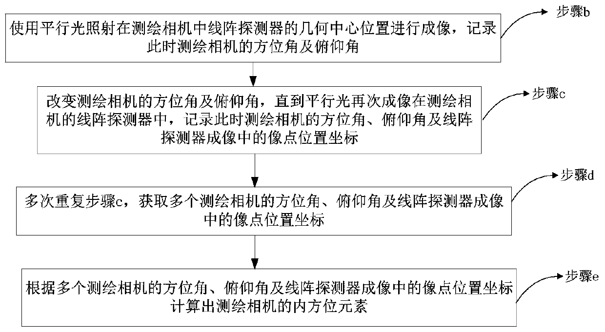
[0077] According to an embodiment of the present invention, a two-dimensional calibration method for orientation elements in a surveying and mapping camera is provided, see image 3 , including the following steps:

[0078] Step b: Use parallel light to illuminate the geometric center of the line array detector in the surveying and mapping camera for imaging, and record the azimuth and elevation angle of the surveying and mapping camera at this time;

[0079]Step c: Change the azimuth and elevation angle of the surveying and mapping camera until the parallel light is imaged in the line array detector of the surveying and mapping camera again, and record the azimuth, elevation angle of the surveying and mapping camera and the image point position in the imaging of the line array detector at this time coordinate;

[0080] Step d: Repeat step c multiple times to obtain the azimuth angles, elevation angles of multiple surveying and mapping cameras and the image point position coo...

Embodiment 2

[0112] According to another embodiment of the present invention, a two-dimensional calibration device for azimuth elements in a surveying camera is provided, see Figure 5 ,include:

[0113] The first recording unit 201 is used to record the azimuth and elevation angle of the surveying and mapping camera at this time after using parallel light to irradiate the geometric center position of the line array detector in the surveying and mapping camera for imaging;

[0114] The second recording unit 202 is used to record the azimuth, elevation angle and line array detection of the surveying and mapping camera at this time after changing the azimuth and elevation angle of the surveying and mapping camera until the parallel light is imaged again in the line array detector of the surveying and mapping camera Image point position coordinates in sensor imaging;

[0115] An acquisition unit 203, configured to record the azimuth angles and elevation angles of multiple surveying and mappi...


PUM


Abstract

The present invention relates to the technical field of aerial surveying and mapping, and in particular to a two-dimensional calibration method and device for azimuth elements in a surveying and mapping camera. The calibration method and device use parallel light to irradiate the geometric center position of the linear array detector in the surveying and mapping camera to perform imaging, and record this Change the azimuth and elevation angles of the surveying and mapping camera at the same time, until the parallel light is imaged again in the line array detector of the surveying and mapping camera, record the azimuth, elevation angle and line array detection of the surveying and mapping camera at this time The image point position coordinates in the sensor imaging, and the internal orientation elements of the surveying and mapping cameras are calculated according to the azimuth and elevation angles of multiple surveying and mapping cameras and the image point position coordinates in the linear array detector imaging. By adjusting the azimuth and elevation angles of the surveying and mapping camera to calibrate the inner azimuth elements, it is ensured that the star point imaging is in the same line array of the surveying and mapping camera, and the precise calibration of the linear array surveying and mapping camera is realized.

Description

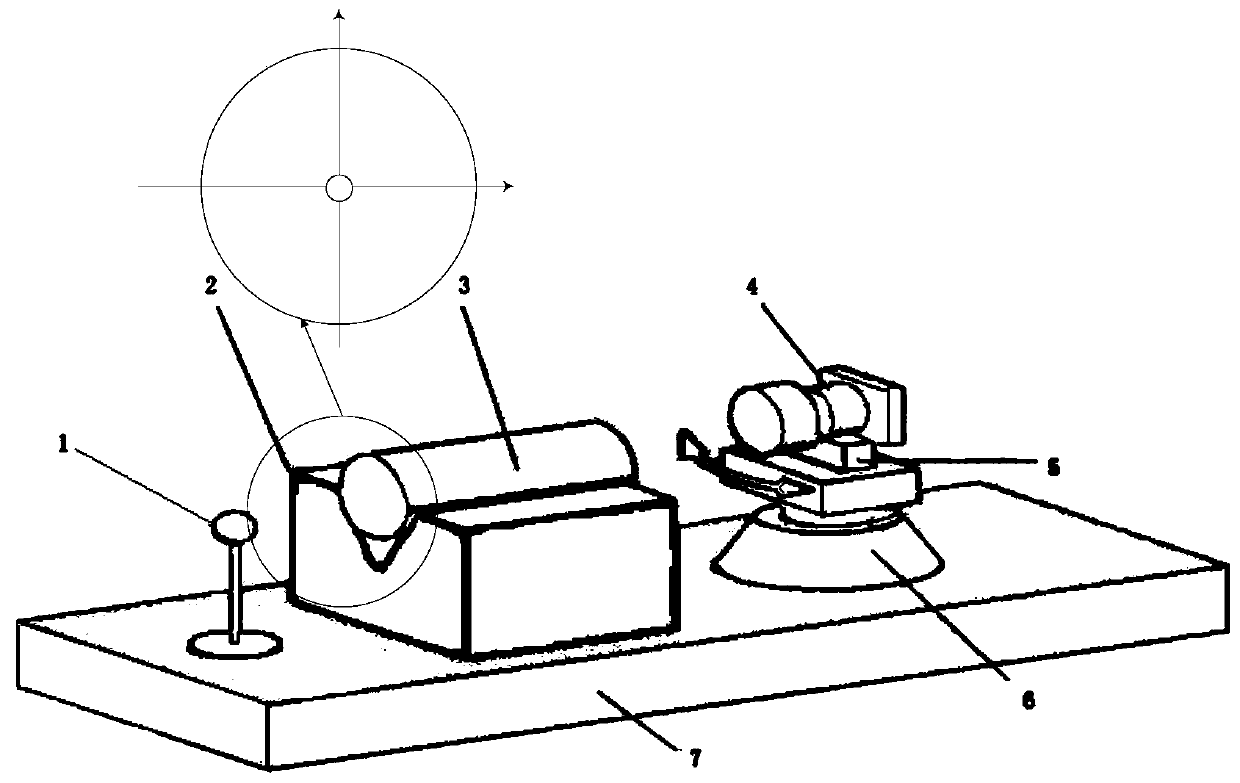
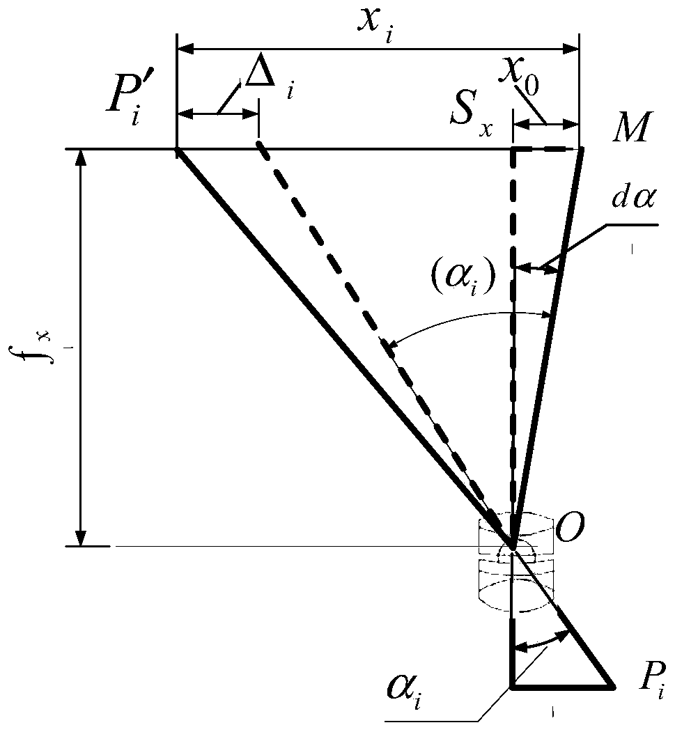
technical field [0001] The invention relates to the technical field of aerial surveying and mapping, in particular to a two-dimensional calibration method and device for orientation elements in a surveying and mapping camera. Background technique [0002] The linear array surveying and mapping camera has the advantages of large base height ratio and high efficiency, and has been widely used in modern aerial surveying and mapping. The linear array surveying and mapping camera needs to be precisely calibrated to the principal point, principal distance, distortion and other internal orientation elements before use. [0003] In the laboratory, the linear array surveying and mapping camera generally adopts the precision goniometric method to calibrate the internal orientation elements. The calibration device to realize this method includes a standard light source 1, a light pipe bracket 2, a collimator 3, a surveying and mapping camera 4, a camera bracket 5, Precision turntable 6...

Claims


Application Information

Patent Timeline
Patent Type & Authority Patents(China)
IPC IPC(8): G01C25/00
Inventor 远国勤郑丽娜张洪文丁亚林孙建军李彬张壮
Owner CHANGCHUN INST OF OPTICS FINE MECHANICS & PHYSICS CHINESE ACAD OF SCI
Learn More