
A non-contact high-precision tool setting system based on optical evanescent waves

A non-contact, high-precision technology, applied in metal processing equipment, measuring/indicating equipment, metal processing machinery parts, etc., can solve problems such as difficult tool calibration, difficult, and inability to form a precise contact interface

Active Publication Date: 2020-07-31
王勇
View PDF5 Cites 0 Cited by
  • Summary
  • Abstract
  • Description
  • Claims
  • Application Information

AI Technical Summary

Problems solved by technology

However, because the existing non-contact tool setting system cannot form an accurate wide-area contact interface, it is also difficult to calibrate the tool with high precision
For example, when using a thin collimated beam for non-contact calibration of a tool, in order to meet the collimation conditions, the diameter of the laser beam will be within the millimeter range, so it cannot meet the micron-level tool calibration requirements in high-precision mechanical equipment
The same problem exists in the blowing non-contact tool setting system, which cannot form an accurate contact interface. Due to the limitation of the field of view, it is difficult for a high-magnification microscope to align a tool whose contact point cannot be determined.

Method used


Image

  • A non-contact high-precision tool setting system based on optical evanescent waves
  • A non-contact high-precision tool setting system based on optical evanescent waves
  • A non-contact high-precision tool setting system based on optical evanescent waves

Examples


no. 1 example

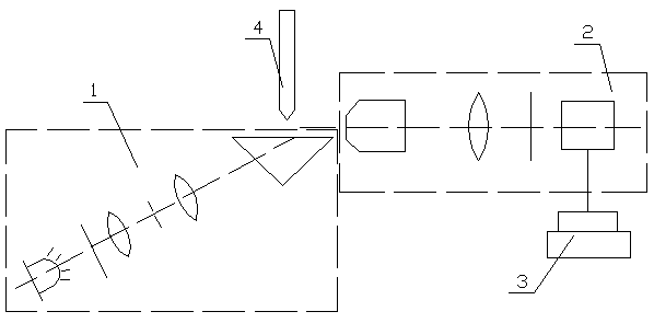
[0029] Such as figure 1 As shown, the present invention discloses a non-contact high-precision tool setting system based on optical evanescent waves, which is used to calibrate the tools 4 in mechanical equipment with high precision, including an evanescent wave generation module 1, a signal detection module 2 and a computer 3, the computer 3 is connected with the signal detection module 2.

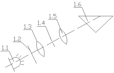
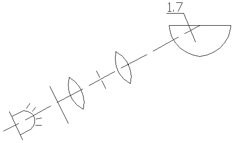
[0030] The evanescent wave generation module in this embodiment is an existing known technology, and there are mainly three different configurations, namely:

[0031] 1) if figure 2 As shown, the evanescent wave generating module 1 of the first configuration includes a first light source 1.1, a first polarization adjuster 1.2, a first convex lens 1.3, a first pinhole 1.4, a second convex lens 1.5 and a triangular prism 1.6, the first light source After the light emitted by 1.1 is adjusted to the P-type polarization state by the polarization adjuster 1.2, it passes through the first con...

no. 2 example

[0048] Such as Figure 7 , 8 , 9, the difference between the second embodiment and the first embodiment is that the optical axis of the signal detection module 2 is parallel to the normal direction of the evanescent wave interface generated by the evanescent wave generation module 1, and the signal detection module 2 It is arranged under the high refractive index medium of the evanescent wave generation module 1, and the objective lens of the signal detection module 2 is vertically facing the lower plane of the high refractive index medium of the evanescent wave generation module 1, and at the same time, the tool 4 enters the evanescent wave generation module 1 After the evanescent electromagnetic field layer, the cutter is within the field of view and depth of field of the objective lens.

[0049] The above-mentioned high refractive index medium is: the triangular prism in the first configuration of the evanescent wave generating module, the hemispherical prism in the second...


PUM


Abstract

The invention discloses a non-contact high-accuracy tool setting system based on an optical evanescent wave, and relates to the equipment field of tool calibration components in high-accuracy mechanical equipment. The non-contact high-accuracy tool setting system based on the optical evanescent wave comprises an evanescent wave generation module, a signal detection module and a computer, wherein the signal detection module comprises an objective lens, a convex lens, a band-pass filter and a signal detector which are sequentially arranged; a tool is capable of slightly touching with an evanescent wave interface at first, and then gradually away from the evanescent wave interface in the normal direction of the evanescent wave interface and according to a given step length, for example, 100nm; because the evanescent wave is exponentially decayed in the normal direction of the interface, after the tool is out of touch with the interface, light intensity generated by acting with the evanescent wave is also exponentially decayed along with the increasing of a distance between the tool and the interface; and therefore, the moving distance of the tool is fitted with the light intensity generated by acting with the evanescent wave, and a position where the tool is just out of touch with the interface can be obtained, so that nanoscale accuracy calibration is realized.

Description

technical field [0001] The invention relates to the equipment field of tool alignment components in high-precision mechanical equipment, in particular to a non-contact high-precision tool setting system based on optical evanescent waves. Background technique [0002] The tool setting system in mechanical equipment, as the calibration component of the equipment processing tool, plays a very important role in improving the qualified rate of one-time workpiece processing, increasing the effective working time of the equipment, and reducing the scrap rate and rework rate of the workpiece. Contact types can be divided into two types: contact and non-contact. For the contact tool setting system, the contact between the tool and the corresponding parts of the tool setting system will inevitably produce a certain degree of elastic deformation at the respective contact parts, resulting in measurement errors, making it difficult for the contact tool setting system to accurately measur...

Claims


Application Information

Patent Timeline
Patent Type & Authority Patents(China)
IPC IPC(8): B23Q17/22B23Q17/24
CPCB23Q17/2428
Inventor 王勇
Owner 王勇
Learn More