Laser driving circuit and method and laser radar system

A technology of driving circuit and driving method, applied in lasers, laser parts, semiconductor lasers, etc., can solve the problems of high cost and large volume

Pending Publication Date: 2019-05-07
LEISHEN INTELLIGENT SYST CO LTD
View PDF0 Cites 9 Cited by
  • Summary
  • Abstract
  • Description
  • Claims
  • Application Information

AI Technical Summary

Problems solved by technology

Because multiple lasers and optical combining devices

Method used


Image

  • Laser driving circuit and method and laser radar system
  • Laser driving circuit and method and laser radar system
  • Laser driving circuit and method and laser radar system

Examples


Embodiment Construction

[0041] The present invention will be further described in detail below in conjunction with the accompanying drawings and embodiments. It should be understood that the specific embodiments described here are only used to explain the present invention, but not to limit the present invention. In addition, it should be noted that, for the convenience of description, only some structures related to the present invention are shown in the drawings but not all structures.

[0042] Terms used in the embodiments of the present invention are only for the purpose of describing specific embodiments, and are not intended to limit the present invention. It should be noted that the orientation words such as "up", "down", "left", and "right" described in the embodiments of the present invention are described from the angles shown in the drawings, and should not be interpreted as a reference to the implementation of the present invention. Example limitations. Also in this context, it also nee...


PUM


Abstract

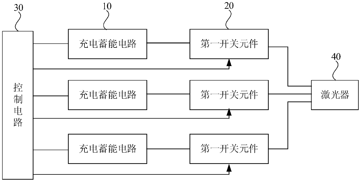
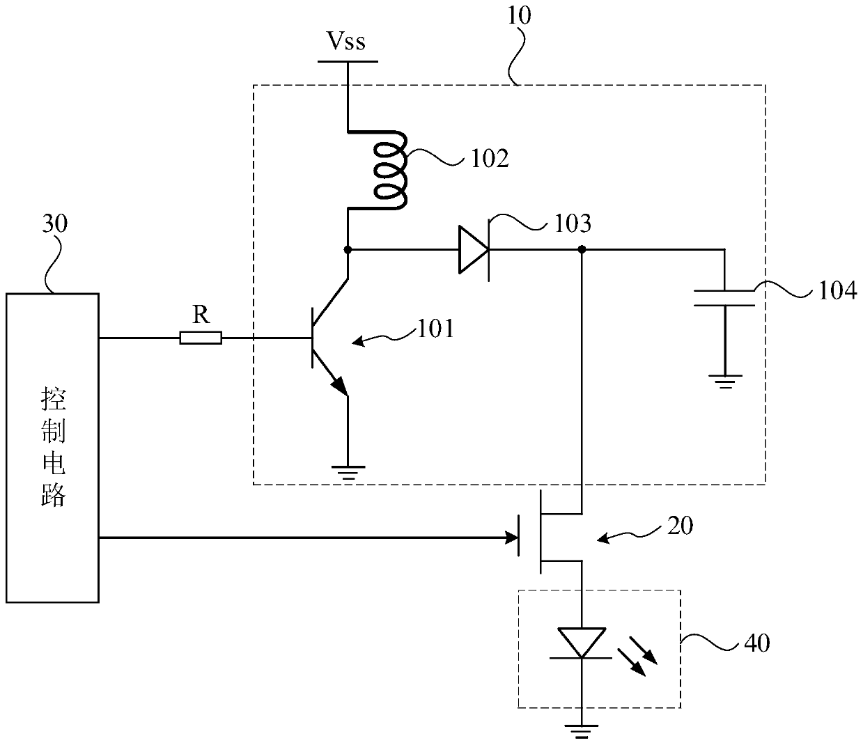
The invention discloses a laser driving circuit and method and a laser radar system. The driving circuit comprises at least two charging energy storage circuits, at least two first switching elementsand a control circuit, wherein the output ends of the charging energy storage circuits are electrically connected with the first ends of the first switching elements in a one-to-one correspondence manner, the second ends of the first switching elements are electrically connected with a laser; the input ends of the charging energy storage circuits and the control ends of the first switching elements are electrically connected with the control circuit; the control circuit charges each charging energy storage circuit for a first preset time, and sequentially controls each first switching elementto be conducted for a second preset time; there is an interval of a third preset time between the charging start time of the subsequent charging energy storage circuit the conduction time of the corresponding first switching element; or the charging start time of each charging energy storage circuit is the same. The technical scheme of the invention improves the transmitting frequency of the laser under the premise of ensuring the pulse power, and solves the contradiction between the transmitting frequency and transmitting power of the laser.

Description

technical field [0001] Embodiments of the present invention relate to laser radar technology, and in particular to a laser driving circuit, a driving method, and a laser radar system. Background technique [0002] With the development of laser technology, laser scanning technology is more and more widely used in fields such as surveying, transportation, driver assistance and mobile robots. Lidar is a radar system that uses laser to detect the position, speed and other characteristic quantities of the target. Its working principle is to first transmit the detection laser beam to the target, and then compare the received signal reflected from the target with the transmitted signal, and make an appropriate After processing, information such as distance, azimuth, height, speed, attitude, and even shape of the target can be obtained. [0003] In order to improve the resolution of the lidar, the laser is required to have a high emission frequency, and the peak power of each pulse...

Claims


Application Information

Patent Timeline
IPC IPC(8): H01S5/042G01S7/484G01S17/02
CPCH01S5/042G01S7/484G01S17/02
Inventor 胡小波沈俭
Owner LEISHEN INTELLIGENT SYST CO LTD
Why Eureka
Try Eureka