
A pole slot design method for multi-frequency anti-pole magnetic field coupling direct-drive doubly-fed motor structure

A field-coupled, doubly-fed motor technology, applied to synchronous motors with stationary armatures and rotating magnets, the shape/style/structure of winding conductors, electromechanical devices, etc., can solve the problem of reducing the power factor and torque of permanent magnet motors. Density, low power factor and torque density, difficult to achieve direct drive and other issues, to achieve the effect of increasing the axial magnetization area, reducing the slot area, and improving the degree of coupling

Active Publication Date: 2020-05-19
NANJING INST OF TECH
View PDF4 Cites 0 Cited by
  • Summary
  • Abstract
  • Description
  • Claims
  • Application Information

AI Technical Summary

Problems solved by technology

However, the high self-inductance and low mutual inductance characteristics of the fractional slot concentrated winding will cause the following problems: the harmonic pole-logarithmic magnetic field rotates at high speed relative to the rotor, and eddy currents will be induced in the permanent magnets, resulting in additional eddy current losses and temperature rise of the permanent magnets , and even cause demagnetization; the electromagnetic weak coupling between the harmonic pole logarithmic magnetic field and the permanent magnet rotor is due to the difference in pole logarithm. Power Factor and Torque Density
Therefore, direct use of such winding schemes for asynchronous induction motors will result in lower power factor and torque density, making it difficult to achieve direct drive

Method used


Image

  • A pole slot design method for multi-frequency anti-pole magnetic field coupling direct-drive doubly-fed motor structure
  • A pole slot design method for multi-frequency anti-pole magnetic field coupling direct-drive doubly-fed motor structure
  • A pole slot design method for multi-frequency anti-pole magnetic field coupling direct-drive doubly-fed motor structure

Examples


Embodiment Construction

[0066] Below in conjunction with accompanying drawing and specific example the present invention is described in further detail.

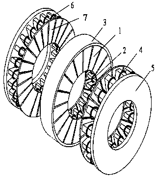
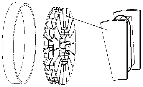
[0067] Such as figure 1 with figure 2 As shown, the structure of multi-frequency opposite-pole magnetic field coupling direct-drive doubly-fed motor with fractional slot concentrated winding includes a stator composed of stator core 1, stator winding 2 and aluminum iron ring 3 fixing the stator core, and the 1# rotor One of the rotors composed of winding 4 and 1# rotor core 5, and the other rotor composed of 2# rotor winding 6 and 2# rotor core 7.

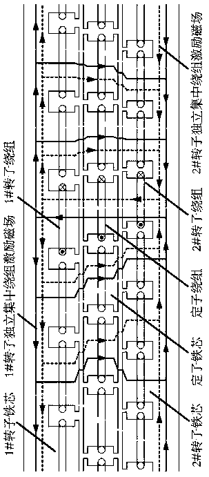
[0068] Both the stator and the two rotors are in the shape of an annular disk, and adopt an axial magnetic field structure. The two rotors are located on both sides of the stator, and there is an air gap between the two rotors and the stator. The generated dominant pole logarithmic harmonic magnetic field is coupled with the magnetic field generated on the two rotors respectively, realizing the low-s...


PUM


Abstract

The invention discloses a multi-frequency paired-pole magnetic field coupling direct-drive doubly-fed motor structure with fractional slot concentrated windings and a pole slot design method. The motor structure comprises a stator composed of a stator core, an aluminum fastener for fixing the stator core and a stator winding, and is characterized in that rotor cores and rotor windings are locatedat two sides of the stator, and the stator and rotor winding coils are wound in an axial space, so that the magnetic conductance of a magnetic path is significantly improved, and the motor diameter isreduced. By using the characteristic that the fractional slot concentrated windings will generate a pair of dominant pole-pair number components, a function of the induction flux linkage and induction voltage of the stator and rotor is constructed by taking the space harmonic magnetic field pole-pair number and slip frequency as independent variables. For different pole slot combinations of the stator and rotor, there is a group of stator and rotor pole slot combinations in which the electromagnetic power transferred by the dominant pole harmonic magnetic field is the highest. The pole slot selection method of the invention improves the power density and power factor, and thus achieves the direct drive / semi-direct drive operation of the motor.

Description

technical field [0001] The invention relates to a structure of a multi-frequency opposite-pole magnetic field coupling direct-drive doubly-fed motor based on fractional slot concentrated windings and a method for selecting pole slots, belonging to the technical field of motors. Background technique [0002] The doubly-fed wind induction generator (the winding form is an integer slot) has a simple and reliable process, and the supporting converter has a small capacity, but the power factor decreases significantly with the increase of the number of pole pairs, and high-speed gears are required for direct drive, which increases the transmission speed. The complexity of the chain seriously affects the system performance. Furthermore, when the power reaches a certain level, the manufacture and maintenance of high-speed gears are extremely difficult. [0003] In this context, the magnetic field modulation permanent magnet gear and the low-speed induction motor system based on the...

Claims


Application Information

Patent Timeline
Patent Type & Authority Patents(China)
IPC IPC(8): H02K16/02H02K21/24H02K3/12
Inventor 许祥威骆皓侍正坤赵家欣侯立军袁威袁野
Owner NANJING INST OF TECH
Learn More