Vibration sieve and method for adopting thick glue to compress and tighten screen

A vibrating screen and vibrating body technology, applied in chemical instruments and methods, filter screens, solid separation, etc., can solve the problems of high viscosity of materials, prolonged vibration time, time-consuming and laborious screen tension, and simplify the operation procedure, Prolonged service life, fast tightening effect

Pending Publication Date: 2019-05-10
山东润科机电设备有限公司
View PDF0 Cites 4 Cited by
  • Summary
  • Abstract
  • Description
  • Claims
  • Application Information

AI Technical Summary

Problems solved by technology

[0008] In the above process of tightening the screen, the screen is manually bent and leveled. However, the screen usually has a certain degree of elasticity. When manually bending, two people need to cooperate tacitly to bend it. Otherwise, the screen is easy to bend during the bending process. Tilting, which requires certain skills of the operator
In addition, when screening some special materials (such as cement), the material is highly viscous and often sticks to the inner wall of the screen frame. It is time-consuming and laborious to tighten the screen for screening such materials. Therefore, when using , if the screen is loose, generally the screen will not be tightened again, and the screen can only be replaced after it is broken
The consequence of this is that the vibration effect of the vibrating screen is not good, and the vibration time is prolonged, which further affects the service life of the entire vibrating screen and vibrating motor.
In the industry, how to quickly, conveniently and effectively tighten the screen has not been a good solution

Method used


Image

  • Vibration sieve and method for adopting thick glue to compress and tighten screen
  • Vibration sieve and method for adopting thick glue to compress and tighten screen
  • Vibration sieve and method for adopting thick glue to compress and tighten screen

Examples


Embodiment 1

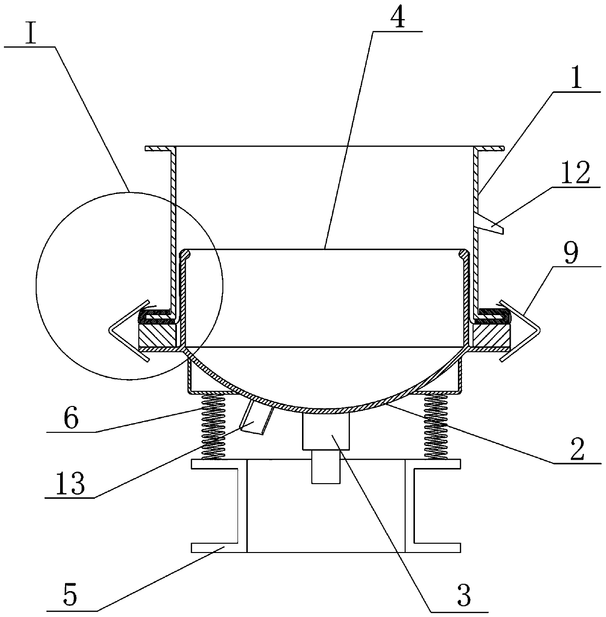
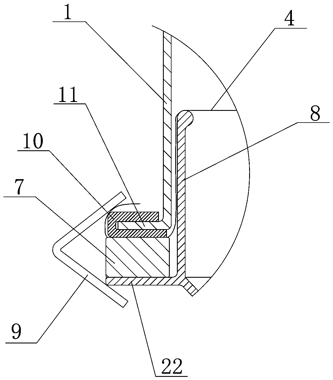
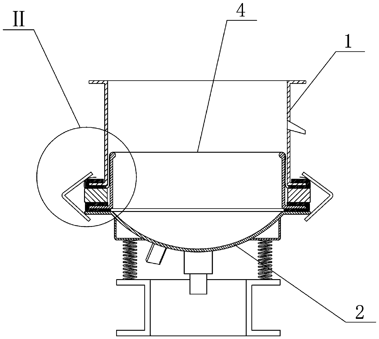
[0036] like figure 1 , 2 As shown, the present embodiment provides a vibrating screen using thick glue to compress and tighten the mesh, which is mainly composed of a screen frame 1, a screen mesh 4, a vibrating body 2, a vibrating motor 3, a base 5, a vibrating spring 6, etc., and the vibrating body 2 It is fixed with the base 5 by the vibration spring 6 . First, an elastic member 7 is placed on the vibrating body locking plate 22, and the elastic member 7 has a sufficient upper and lower elastic compression margin. The vibrating body 2 is provided with a grid 8, and the grid 8 can be fixed on the inner wall of the vibrating body 2 by welding; The locking plate 11 and the vibrating body locking plate 22 have a certain margin. The edge of the screen frame locking plate 11 is wrapped with a U-shaped rubber ring 10, and the screen frame locking plate 11 presses the edge of the screen 4 on the vibrating body locking plate 22, and at the same time tries to ensure that the scree...

Embodiment 2

[0041] Compared with the first embodiment, the grid frame in this embodiment can adopt the finished grid frame 14 currently on the market. like image 3 , Figure 4 As shown, the finished mesh frame 14 has a bottom edge. First, the bottom edge of the finished mesh frame 14 is wrapped with a U-shaped rubber ring 15 to avoid material leakage, and then the bottom edge of the mesh frame 8 is placed on the vibrating body locking plate 22. Then, the elastic member 7 is placed on it, and other structures are the same as those of the first embodiment.

[0042] The grid 8 in the first embodiment is prone to problems such as skew and poor welding when it is fixed with the inner wall of the vibrating body 2, which requires welding technology, and the present embodiment adopts the existing finished grid 14 on the market, which is convenient for production. It can also ensure the flatness of the support end of the grid.

Embodiment 3

[0044]Compared with Embodiment 1, the elastic member in this embodiment can be replaced by a spring 16 and an annular sealing ring 17 . like Figure 5 , Image 6 As shown, a coil of spring 16 is arranged on the vibrating body locking plate 22. The function of the spring 16 is the same as that of the elastic member 7 in the first embodiment, and both have a certain upper and lower elastic compression margin. An annular sealing ring 17 is arranged above the spring 16, and the inner wall of the annular sealing ring 17 is closely attached to the outer wall of the network frame 8 to prevent material from leaking. Subsequently, the screen cloth 4, the screen frame 1, etc. are set above the annular sealing ring 17, the same as in the first embodiment.

[0045] In this embodiment, the elastic part is replaced by a spring, which provides another solution to the elastic compression margin, and can also realize the tightening of the screen only through the locking of the screen frame a...


PUM


Abstract

The invention belongs to the technical field of material screening, and particularly relates to a vibration sieve and a method for adopting thick glue to compress and tighten a screen. A sieve frame,a screen, a screen frame and a vibration body are included. Locking discs are arranged on the edge of the sieve frame and the edge of the vibration body. The screen is laid on the screen frame, and the edge of the screen is tightly pressed below the sieve frame locking disc. The sieve frame, the screen frame, the screen and the vibration body are fixed together at the outer portion through fasteners. The vibration sieve and the method for adopting the thick glue to compress and tighten the screen are characterized in that elastic pieces with upper and lower elasticity are further included, andthe elastic pieces are arranged below the part, above the vibration body locking disc, of the screen. According to the vibration sieve and the method, the screen can be tightened directly through locking of the fasteners at the outer portion, and operation is simple and convenient.

Description

technical field [0001] The invention belongs to the technical field of material screening, and in particular relates to a vibrating screen and a method for compressing and tightening a mesh with thick glue. Background technique [0002] Enterprises widely use vibrating screens to sort materials. Commonly used vibrating screens include screen frames, mesh frames, vibrating bodies, screen meshes, mesh hoops, vibrating springs connected to the vibrating bodies, vibrating motors and other structural components. By starting the vibrating motor To drive the vibrating body, the screen mesh and the screen frame to vibrate up and down together, so that the small particle material leaks through the screen mesh, and the large particle material is blocked on the screen mesh. The screen used in the vibrating screen is generally made of metal wire, nylon wire, etc., and the screen is easily loosened by the falling effect of the material during the vibration process. The important factor ...

Claims


Application Information

Patent Timeline
Patent Type & Authority Applications(China)
IPC IPC(8): B07B1/28B07B1/48
Inventor 赵维珂
Owner 山东润科机电设备有限公司
Why Eureka
Try Eureka