
Municipal garden soil treatment device

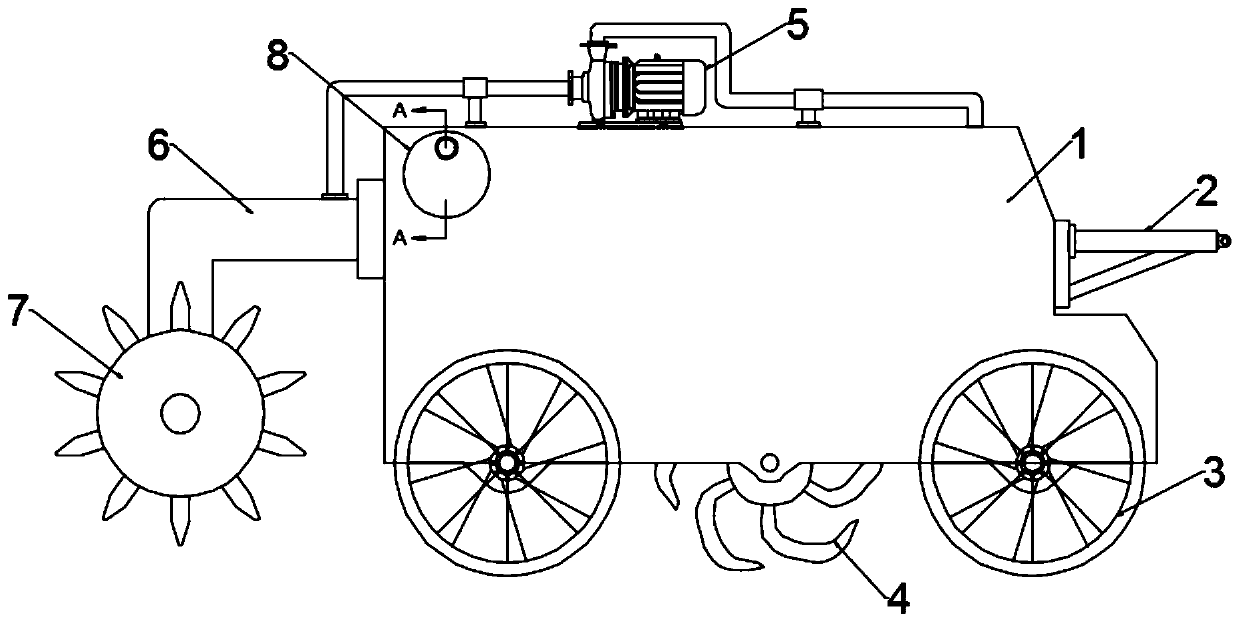
A garden and soil technology, applied in the restoration of polluted soil, shovels, plows, etc., can solve the problems of inability to meet rapid treatment, low treatment efficiency, etc., and achieve the effect of good treatment effect, novel design and high treatment efficiency.

Inactive Publication Date: 2019-05-10
陈师颖
View PDF0 Cites 3 Cited by
  • Summary
  • Abstract
  • Description
  • Claims
  • Application Information

AI Technical Summary

Problems solved by technology

[0004] The existing soil treatment device is to transport the soil into the treatment device and mix it with the treatment solution before laying it on the garden. The treatment efficiency in this way is low and cannot meet the requirements of rapid treatment.

Method used


Image

  • Municipal garden soil treatment device
  • Municipal garden soil treatment device
  • Municipal garden soil treatment device

Examples


Embodiment 2

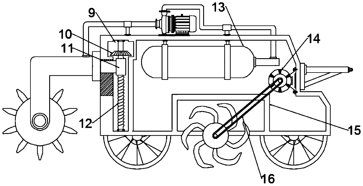
[0036] During soil treatment, it is necessary to treat soils of different depths according to different environmental requirements to improve the treatment effect. Therefore, in the specific implementation process of the present invention, another embodiment is proposed to improve the application. Specifically, It includes an adjustment component for adjusting the height of the bracket 6.

[0037] The adjustment component includes:

[0038] The adjustment cavity 9 is arranged at the inner end of the casing 1, and the side end is provided with a through slot penetrating the casing 1;

[0039] The threaded rod 12 is rotatably installed in the adjustment cavity 9, and a threaded sleeve 11 is threadedly connected to it. The threaded sleeve 11 is fixedly connected to the bracket 6 through a connecting block penetrating through the groove. The threaded rod 12 is rotated through a threaded sleeve The function of the barrel 11 and the connecting block drives the bracket 6 to adjust the up a...

Embodiment 3

[0042] The soil is relatively compact after being used for a period of time, and it is easy to cause damage to the liquid injection head by inserting the liquid injection component into the soil alone. Therefore, in the specific implementation process of the present invention, another embodiment is proposed to improve the application. Specifically, The rotary tiller 4 is also included. The rotating shaft of the rotary tiller 4 is rotatably connected with the output shaft of the motor 14 installed on the inner wall of the casing 1 through a transmission belt 16. When the motor 14 rotates, the rotary tiller 4 is driven to rotate, thereby loosening the soil. deal with.

[0043] In order to effectively prevent soil from splashing into the inside of the casing 1 during the rotary tillage process, therefore, in the specific implementation of the present invention, a protective cover 15 fixedly connected to the casing 1 is provided above the rotary tiller 4.

[0044] In order to facilitat...


PUM


Abstract

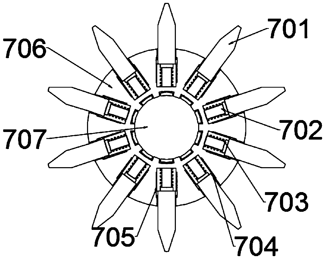
The invention relates to the technical field of environmental protection equipment, in particular to a municipal garden soil treatment device, which comprises a liquid injection component, wherein theliquid injection component is mounted on a bracket connected with a machine shell in a rotary manner; the liquid injection component comprises a plurality of liquid injection heads, push plugs and arotary disc; a storage cavity is formed in the inner side of the rotary disc; the storage cavity is communicated with an empty cavity formed in the inner side of the bracket through a rotary joint; aplurality of the liquid injection heads are axially arranged on the rotary disc, and the liquid injection heads are inserted into a movable groove formed in the rotary disc and are connected with themovable groove in a sliding manner; the push plugs penetrate through a connecting arm of the movable groove and the storage cavity and are abutted with the liquid injection heads; and springs for resetting are sleeved outside the push plugs positioned in the movable groove. When the liquid injection heads are abutted against the soil, the liquid injection heads move to the inner side of the movable groove under the action of soil resistance, so as to push the push plugs to move, and a treatment liquid inside the storage cavity enters the liquid injection heads and enters the soil through the liquid injection heads to realize the effect of soil treatment.

Description

Technical field [0001] The invention relates to the technical field of environmental protection equipment, in particular to a municipal garden soil treatment device. Background technique [0002] Soil treatment, namely soil remediation, soil remediation is a technical measure to restore normal functions of contaminated soil. In the soil remediation industry, there are more than one hundred kinds of soil remediation technologies, and there are also more than ten commonly used technologies, which can be roughly divided into three methods: physical, chemical and biological. Since the 1980s, many countries in the world, especially developed countries, have formulated and carried out contaminated soil treatment and remediation plans, thus forming a new soil remediation industry. [0003] With "high pollution exceeding rate", "trillion-level market", "complex systems engineering", and "emerging industries in the early stage of development", China's soil pollution prevention and control ...

Claims


Application Information

Patent Timeline
IPC IPC(8): B09C1/08B09C1/00A01B49/02
Inventor 陈师颖
Owner 陈师颖
Learn More