
Automatic feeding device and method of riveting column for riveting charging connector

A charging connection and pressing device technology, applied in metal processing, metal processing equipment, manufacturing tools, etc., can solve the problems of low precision, low fixture circulation efficiency, low assembly precision, etc., to improve efficiency and precision, facilitate The effect of integrated processing and convenient and efficient assembly

Inactive Publication Date: 2019-05-10
李琼
View PDF6 Cites 0 Cited by
  • Summary
  • Abstract
  • Description
  • Claims
  • Application Information

AI Technical Summary

Problems solved by technology

Most of the existing production methods are semi-automated and assembled manually. The shortcomings of the existing technology are: 1. Slow feeding of the substrate, low efficiency, and low precision; 2. Low circulation efficiency and poor precision of the fixture; 3. . It is difficult to clamp the material on the clamping shell, and the efficiency is low; 4. The rivet column parts are small, difficult to clamp, variable, and low in assembly accuracy; 5. The separation between the fixtures of the workpiece is complicated, and the tooling structure is complicated

Method used


Image

  • Automatic feeding device and method of riveting column for riveting charging connector
  • Automatic feeding device and method of riveting column for riveting charging connector
  • Automatic feeding device and method of riveting column for riveting charging connector

Examples


Embodiment Construction

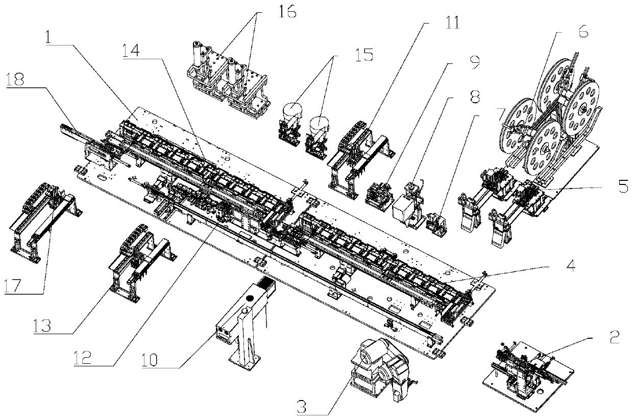
[0041] Such as figure 1As shown, the described charging connector automatic assembly equipment includes a frame 1 and a substrate feeding device 2 installed on the frame 1, a mechanical arm handling device 3, a clamping fixture circulation device 4, and a lower clamping device. Feeding device 5, upper shell feeding device 6, shell pressing device 7, shell detection device 8, shell bending device 9, shell welding device 10, first conveying device 11, substrate jig reflow device 12 , the second handling device 13, the riveting jig circulation device 14, the riveting column feeding device 15, the riveting column pressing device 16, the third handling device 17 and the product unloading device 18; the substrate feeding device 2 is used to place the substrate Put it into the base jig, and feed the base together with the base jig; the mechanical arm handling device 3 is connected with the base feeding device 2, and is used to transport the base jig to the clamping jig circulation de...


PUM


Abstract

The invention relates to the field of production and manufacture of charging products, in particular to an automatic feeding device and method of a riveting column for riveting a charging connector. The automatic feeding device of the riveting column for riveting the charging connector comprises a circular vibrator, a straight vibrator, a feeding rail plate, a twenty-second base, a riveting columnreceiving plate, a thirty-fifth air cylinder, a thirty-sixth air cylinder, a twenty-third base, a jacking mechanism and a feeding mechanism, wherein the feeding rail plate is provided with two feeding grooves, the end parts of the feeding grooves are provided with circular holding holes, thin grooves are formed in the feeding rail plates, and four round holes are formed in the end part of the feeding rail plate in pairs; the jacking mechanism comprises a thirty-seventh air cylinder and a jacking rod; and the feeding mechanism comprises a thirty-eighth air cylinder and a feeding piece. According to the riveting column feeding device, ordered feeding is realized through vibration, the special riveting column receiving plate is provided and used for temporarily storing the riveting column and keeping the posture of the riveting column, the riveting column can be moved and transported by moving the riveting column receiving plate, and finally, the assembling efficiency and precision are improved through riveting and pressing.

Description

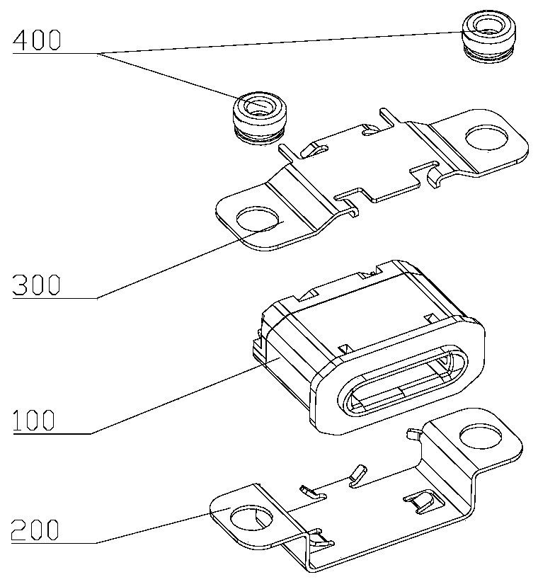
technical field [0001] The invention relates to the field of charging product manufacturing, in particular to an automatic feeding device and method for riveting posts used for riveting charging connectors. Background technique [0002] The charging connector is one of the components connected to the electrical circuit, which realizes the signal transmission between two devices, such as the telephone line wiring structure, the network line wiring structure, etc. It is mainly to insert a signal transmission line into the electronic connector with fixed specifications. Structurally, it is generally divided into one male and one female. The connector is structurally composed of a base body, a shell and a rivet post, the shell is used for the base body, and the base body is used for wiring. Most of the existing production methods are semi-automated and assembled manually. The shortcomings of the existing technology are: 1. Slow feeding of the substrate, low efficiency, and low ...

Claims


Application Information

Patent Timeline
IPC IPC(8): B23P19/027
Inventor 李琼陈荣乾李柯
Owner 李琼
Learn More