A pneumatic transfer robot
A technology of robots and power mechanisms, which is applied in the direction of manipulators, program-controlled manipulators, manufacturing tools, etc., can solve problems such as the inability to realize low-cost transshipment of goods, and achieve the effects of improving cargo transshipment efficiency, good maintainability, and easy maintenance
- Summary
- Abstract
- Description
- Claims
- Application Information
AI Technical Summary
Problems solved by technology
Method used
Image
Examples
specific Embodiment approach 1
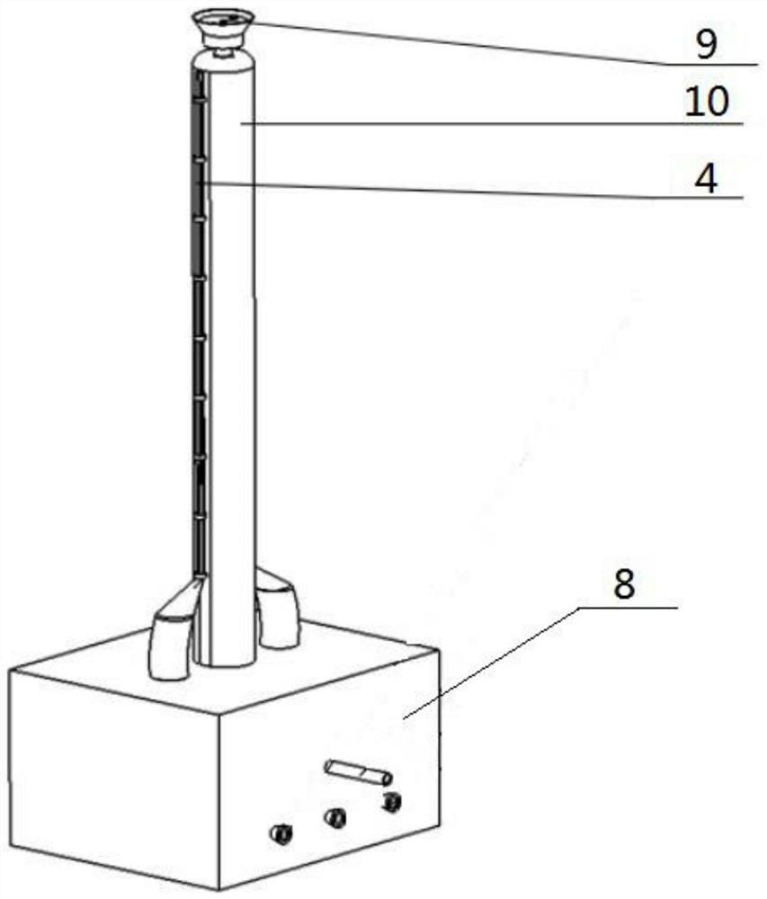
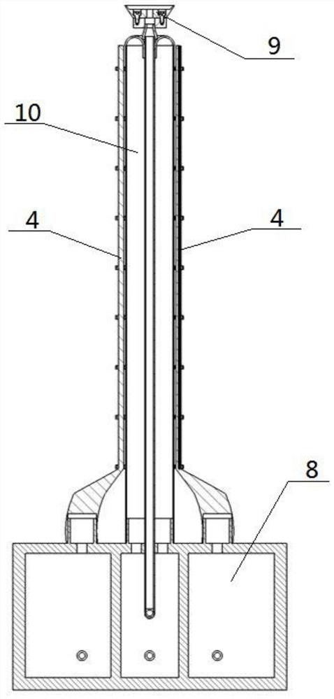
[0032] Such as Figure 1-7 As shown, a pneumatic transfer robot includes a power mechanism 8, a steering unit 4, a grasping device 9 and a soft robot body 10. The steering unit 4 is provided with two groups, and the two groups of steering units 4 are respectively fixedly connected to the soft robot body. the left and right ends of 10; the middle end of the grasping device 9 passes through the middle end of the inner side of the soft robot body 10, and the upper end of the grasping device 9 is located at the top of the soft robot body 10; the soft robot body 10, the grasping device 9 and the lower ends of the two groups of steering units 4 are fixedly connected to the power mechanism 8, and the power mechanism 8 drives and controls the main body 10 of the soft robot, the grasping device 9 and the two groups of steering units 4. The pneumatic transfer robot described above, when in use, the power source of the power mechanism 8 is an air source or a hydraulic source, and the ste...
specific Embodiment approach 2
[0034] Such as Figure 1-7 As shown, the main body 10 of the soft robot includes a soft airbag II3 and an airbag II ventilation hose, and the port I of the soft airbag II3 is sealed and connected to one end of the airbag II ventilation hose through a joint; the port II of the soft airbag II3 is turned inside out and It is fixedly connected inwardly to the port I of the soft airbag II3, the inner side of the soft airbag II3 forms a hose channel, and the other end of the airbag II ventilation hose is connected to the power mechanism 8.
[0035] When the soft robot body 10 is in use, it can inflate the interior of the airbag II ventilation hose through the power mechanism 8 and inflate the interior of the soft airbag II3 through the airbag II ventilation hose, so that the length of the soft airbag II3 changes, which is convenient to match the airbag II. Each steering unit 4 performs the transshipment work of the goods 5 to be transshipped.
specific Embodiment approach 3
[0037] Such as Figure 1-7 As shown, the steering unit 4 includes a soft airbag I1, a throttle ring 2 and an airbag I ventilation hose, and the throttle ring 2 is provided with multiple, and a plurality of throttle rings 2 are equally spaced on the soft airbag I1 and connected with the soft airbag. I1 is fixedly connected; the soft airbag I1 is fixedly connected on the side of the soft airbag II3; one end of the soft airbag I1 and the airbag I ventilation hose is sealed and connected by a joint, and the other end of the airbag I ventilation hose is connected to the power mechanism 8.
[0038] When the steering unit 4 is in use, the elastic-plastic deformation of the soft airbag I1 will not occur under normal air pressure, which ensures that the volume of the soft airbag I1 remains unchanged. Since the diameter of the throttle ring 2 is smaller than the soft airbag I1, when the power mechanism 8 passes through the airbag I When the ventilation hose is inflated into the soft air...
PUM
 Abstract
Description
Claims
Application Information
 - R&D
- Intellectual Property
- Life Sciences
- Materials
- Tech Scout
- Unparalleled Data Quality
- Higher Quality Content
- 60% Fewer Hallucinations
Browse by: Latest US Patents, China's latest patents, Technical Efficacy Thesaurus, Application Domain, Technology Topic, Popular Technical Reports.
© 2025 PatSnap. All rights reserved.Legal|Privacy policy|Modern Slavery Act Transparency Statement|Sitemap|About US| Contact US: help@patsnap.com


