Tethered underwater lifting platform

A lifting platform and mooring technology, which is used in underwater operation equipment, hull, ship construction, etc., can solve the problems of large horizontal drag force, high power consumption, intermittent time dimension and space dimension of sampled data, etc., and achieve the lifting speed. Stable, stable data collection, long stroke effect

Active Publication Date: 2020-12-08
QINGDAO NAT LAB FOR MARINE SCI & TECH DEV CENT +1
View PDF8 Cites 0 Cited by
  • Summary
  • Abstract
  • Description
  • Claims
  • Application Information

AI Technical Summary

Problems solved by technology

[0004] After many years of use, the current underwater tethered vertical lifting platform has problems such as short travel within the battery capacity cycle and unevenness of collected data.
Under the action of unsteady and strong ocean currents in the horizontal direction, the horizontal drag force on the platform will be very large, and it will swing at a certain large angle and frequency. Because the instruments such as CTD temperature, salinity and depth instrument and ACM current meter are integrated with compass And other attitude sensors, CTD and ACM will stop sampling work when the swing range is large, so that the entire sampling data will appear intermittent in time and space dimensions, and the tilting swing of the platform will also cause the power of the motor in the drive part If the power consumption is too high, it will affect the total stroke of the vertical lift

Method used


Image

  • Tethered underwater lifting platform
  • Tethered underwater lifting platform
  • Tethered underwater lifting platform

Examples


Embodiment 1

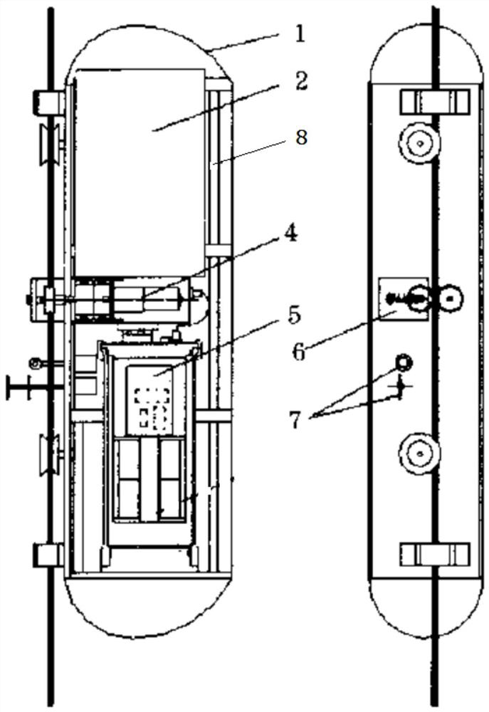
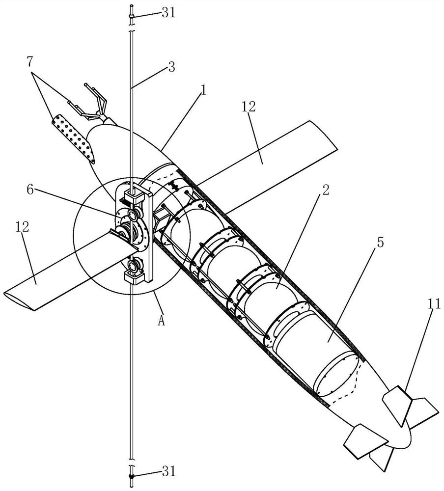
[0042] see figure 2 , image 3 As shown, the tethered underwater lifting platform includes a platform part 1, a driving part 4 and a moving part 6, wherein the driving part 4 is connected to the moving part 6 to drive the moving part 6 to move up and down along the mooring cable 3, and the platform part 1 It is rotatably connected with the moving part 6. When the moving part 6 moves up and down in the water along the mooring cable, it can drive the platform part 1 to rise and fall together. The platform part 1 is equipped with multiple types of sensors 7, and the sensors 7 perform circular and continuous profile measurements on the ocean during the lifting movement.

[0043] Further, the tethered underwater lifting platform also includes a tethered cable 3, and the two ends of the tethered cable 3 are connected with a universal swivel 31. The universal swivel 31 can realize the two-dimensional 360° rotation of the platform part 1, and the platform part 1 can rotate freely u...

Embodiment 2

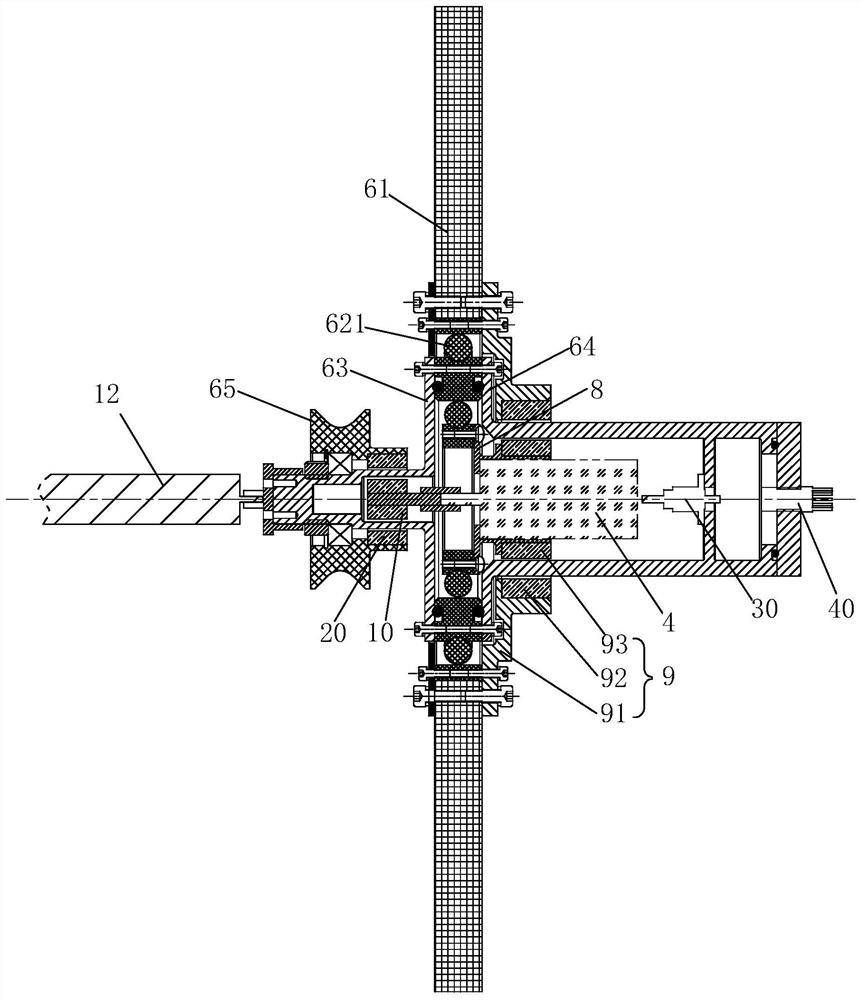
[0057] see Figure 6As shown, the difference from Embodiment 1 is that the rotational connection between the platform part 1 and the moving part 6 is realized through the second bearing 622, and the second bearing 622 has two layers of an outer ring and an inner ring. Specifically, a cylindrical protrusion 611 is provided on the right side of the vertical plate 61 , and the second bearing 622 is sleeved outside the cylindrical protrusion 611 . The vertical plate 61 is fixedly connected to the outer ring of the second bearing 622 , and the sealing housing 64 is fixedly connected to the inner ring of the second bearing 622 , so as to realize the rotational connection between the platform part 1 and the moving part 6 .

[0058] Specifically, the driving part 4 is fixedly connected to the vertical plate 61 through the flange 8, so that the driving of the driving wheel 65 by the driving part 4 and the rotation of the platform part 1 relative to the moving part 6 do not interfere wi...

Embodiment 3

[0060] see Figure 7 As shown, the difference from Embodiment 2 is that the right side surface of the vertical plate 61 is provided with an annular groove 612, the left end of the sealing housing 64 is inserted into the annular groove 612, and the sealing housing 64 is provided with a protrusion 641 , the vertical plate 61 is provided with an annular groove 613 that cooperates with the protrusion 641, and the annular groove 613 cooperates with the protrusion 641, which can limit the horizontal movement of the sealing shell 64 and realize the contact between the platform part 1 and the moving part 6 Turn to connect.


PUM


Abstract

The invention discloses a moored underwater lifting platform and belongs to the technical field of underwater observation. The moored underwater lifting platform comprises a platform part, a moving part and a driving part, wherein the moving part can lift along a mooring rope, and the driving part can drive the moving part to lift along the mooring rope; and the platform part is rotationally connected with the moving part. The moored underwater lifting platform has the advantages of long travel, stable collected data and stable lifting speed within a battery capacity period.

Description

technical field [0001] The invention belongs to the technical field of underwater observation and detection, and in particular relates to a tethered underwater lifting platform. Background technique [0002] Because the physical, chemical and biological properties of water in the ocean vary with depth and time, it is required to develop a measurement device that can perform long-term, continuous profiles in a certain sea area. The traditional and widely used surveying devices are array moored buoys and Argo profiling drifting buoys. The working principle of the array moored buoy is to lay out the buoy body on the sea surface and the anchor spindle on the seabed. The buoy body and the anchor spindle are connected by connecting cables to mount various sensors in an array to measure various types of water bodies for a long time. As the water depth increases, the number of sensors carried by this array mooring buoy also increases accordingly, resulting in extremely high cost of...

Claims


Application Information

Patent Timeline
Patent Type & Authority Patents(China)
IPC IPC(8): B63C11/52B63B1/32B63B21/20
CPCY02T70/10
Inventor 赵龙吴国俊杭栋栋焉兆超李亚辉王东升
Owner QINGDAO NAT LAB FOR MARINE SCI & TECH DEV CENT
Why Eureka
Try Eureka