Counterweight type roller transfer device capable of being opened and closed

The technology of conveying device and drum is applied in the field of counterweight openable and closable drum conveying device, which can solve the problems of high cost, time-consuming and laborious, low efficiency, etc., and achieve the effects of improving tooling efficiency, wide application range and convenient use.

Active Publication Date: 2019-05-10
YANSHAN UNIV
View PDF6 Cites 2 Cited by
  • Summary
  • Abstract
  • Description
  • Claims
  • Application Information

AI Technical Summary

Problems solved by technology

[0002] With the development of modernization, most factories adopt assembly line production. At present, most of the delivery links of woven bags or boxed goods require manual standing on the tooling truck to stack the goods. The long-term operation is labor-intensive, time-consuming and labor-intensive, and the efficiency is high. On the low side, the working environment of some tooling links is not good and there are potential safety hazards
[0003] Although some large-scale tooling links have been equipped with equipment, the existing equipment and tooling have poor adaptability and cannot adapt to various workpieces with large size changes for operation, and because of their complex structures, the cost is high and the work efficiency is high. Low cost, time-consuming handling, virtually increases the operating cost of the enterprise, generally only used in large-scale tooling links, most of the existing tooling equipment uses grabbing robots, the tooling function is single, and the ability to grab objects is not stable enough, and The structure is not flexible enough, the grasping force is not easy to control, and it is easy to cause damage to the outer packaging

Method used


Image

  • Counterweight type roller transfer device capable of being opened and closed
  • Counterweight type roller transfer device capable of being opened and closed
  • Counterweight type roller transfer device capable of being opened and closed

Examples


specific Embodiment

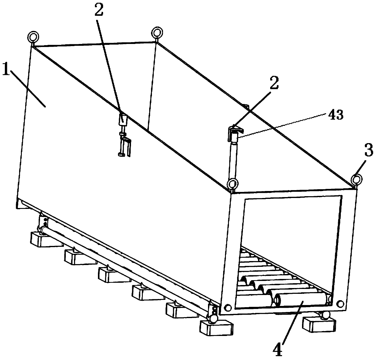
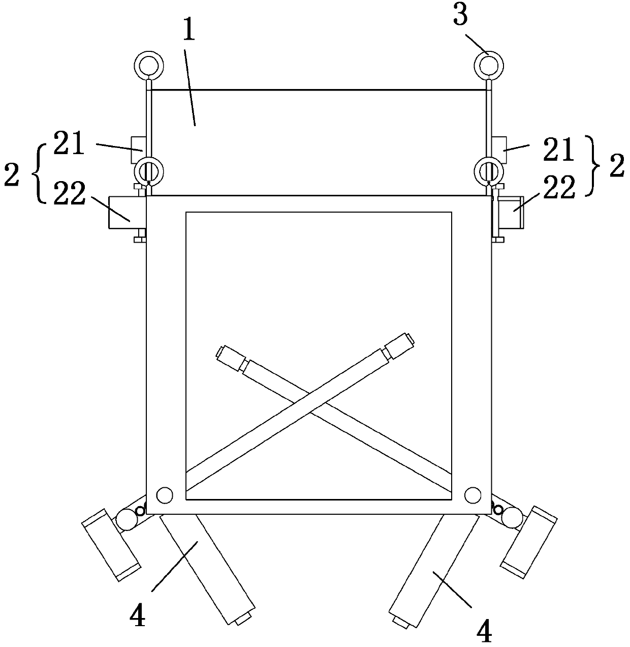
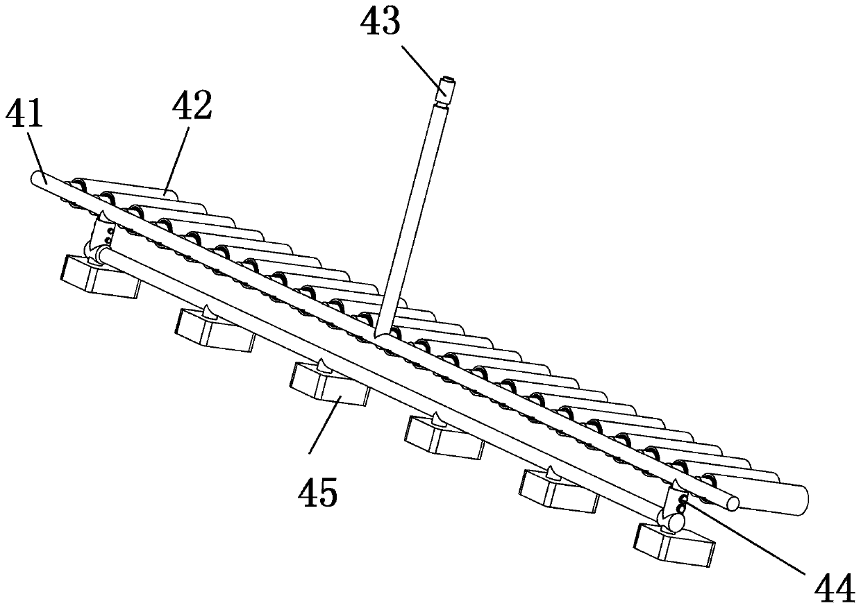
[0039] Such as figure 1 As shown, the present invention provides a counterweight type openable roller conveyor, which includes a tooling bucket 1 , a pair of rotating locking devices 2 , four suspension rings 3 and a pair of counterweight roller conveyor belts 4 . Two rotation locking devices 2 are respectively arranged on opposite side walls of the tooling bucket 1 . Four suspension rings 3 are respectively fixed on the top of the four corners of the tooling bucket 1 .

[0040] The rotation locking device 2 includes a steering gear 21 and a locking chuck 22, the steering gear 21 and the locking chuck 22 are connected by a rotating shaft, and the steering gear 21 can drive the locking chuck 22 to rotate.

[0041]The entire tooling device is connected to the crane through the lifting ring 3. Under normal working conditions, the bottom surface of the tooling bucket 1 forms an included angle of 15 degrees with the horizontal surface to ensure that the goods slide down without dr...


PUM


Abstract

The invention provides a counterweight type roller transfer device capable of being opened and closed. The counterweight type roller transfer device capable of being opened and closed comprises a toolhopper and a counterweight roller conveyor belt unit, wherein a rotary locking device is separately arranged on the two side parts opposite to the tool hopper; the counterweight roller conveyor beltunit comprises two counterweight roller conveyor belts which are symmetrically arranged; each counterweight roller conveyor belt comprises a rotary shaft, a conveying roller, a rolling sleeve, a pin and a counterweight block, wherein the counterweight block is connected with the rotary shaft through the pin, the conveying roller is arranged on the rotary shaft, the rolling sleeve is vertically arranged on the rotary shaft; and each rotary locking device is in contact with the counterweight roller conveyor belt unit by being indirectly in contact with the corresponding rolling sleeve. Accordingto the counterweight type roller transfer device disclosed by the invention, goods can enter the tool hopper without drive, automatically glide and are automatically stacked in the tool hopper; and moreover, multiple goods can be placed once, so that tool efficiency is greatly improved. The counterweight type roller transfer device has the characteristics of being simple in structure, relativelylow in cost, wide in scope of application, simple in operation, convenient in use, and the like.

Description

technical field [0001] The invention relates to the technical field of tooling equipment, in particular to a counterweight type openable and closable roller conveying device. Background technique [0002] With the development of modernization, most factories adopt assembly line production. At present, most of the delivery links of woven bags or boxed goods require manual standing on the tooling truck to stack the goods. The long-term operation is labor-intensive, time-consuming and labor-intensive, and the efficiency is high. On the low side, the operating environment of some tooling links is not good and there are potential safety hazards. [0003] Although some large-scale tooling links have been equipped with equipment, the existing equipment and tooling have poor adaptability and cannot adapt to various workpieces with large size changes for operation, and because of their complex structures, the cost is high and the work efficiency is high. Low cost, time-consuming han...

Claims


Application Information

Patent Timeline
Patent Type & Authority Applications(China)
IPC IPC(8): B65D88/54B65D90/00B65D90/54B65D90/66
Inventor 侯雨雷余鹏邓云蛟许海彪胡树勤曾达幸王航窦玉超吴华芳张继永赵西宏
Owner YANSHAN UNIV
Why Eureka
Try Eureka