Refueling gun and refueling equipment

A fueling gun and equipment technology, applied in special dispensing devices, packaging, dispensing devices, etc., can solve the problems of affecting the refueling operation, increasing the frictional resistance between the sealing ring and the shaft sleeve, and the short life, so as to improve the use feeling and reduce the Effects of frictional resistance and life extension

Pending Publication Date: 2019-05-10
苏州三米格环保科技有限公司
View PDF12 Cites 2 Cited by
  • Summary
  • Abstract
  • Description
  • Claims
  • Application Information

AI Technical Summary

Problems solved by technology

Due to the limitation of process difficulty and cost, the inner surface of the shaft sleeve is relatively rough, so when the sealing ring is in contact with the inner surface of the shaft sleeve and undergoes relative motion, the sealing ring suffers from large frictional resistance, and the sealing ring wears quickly, resulting in a short service life
After a long period of use, due to the wear of the sealing ring, the sealing performance of the gas circuit will decrease, which will affect the conventional refueling operation
In addition, due to the long-term contact of the sealing ring in the shaft sleeve with fuel, the sealing ring will expand, which will further increase the frictional resistance between the sealing ring and the shaft sleeve, and accelerate the wear of the sealing ring, resulting in the need to press the trigger switch. The force increases, which affects the normal use of the user

Method used


Image

  • Refueling gun and refueling equipment
  • Refueling gun and refueling equipment
  • Refueling gun and refueling equipment

Examples


Embodiment approach 1

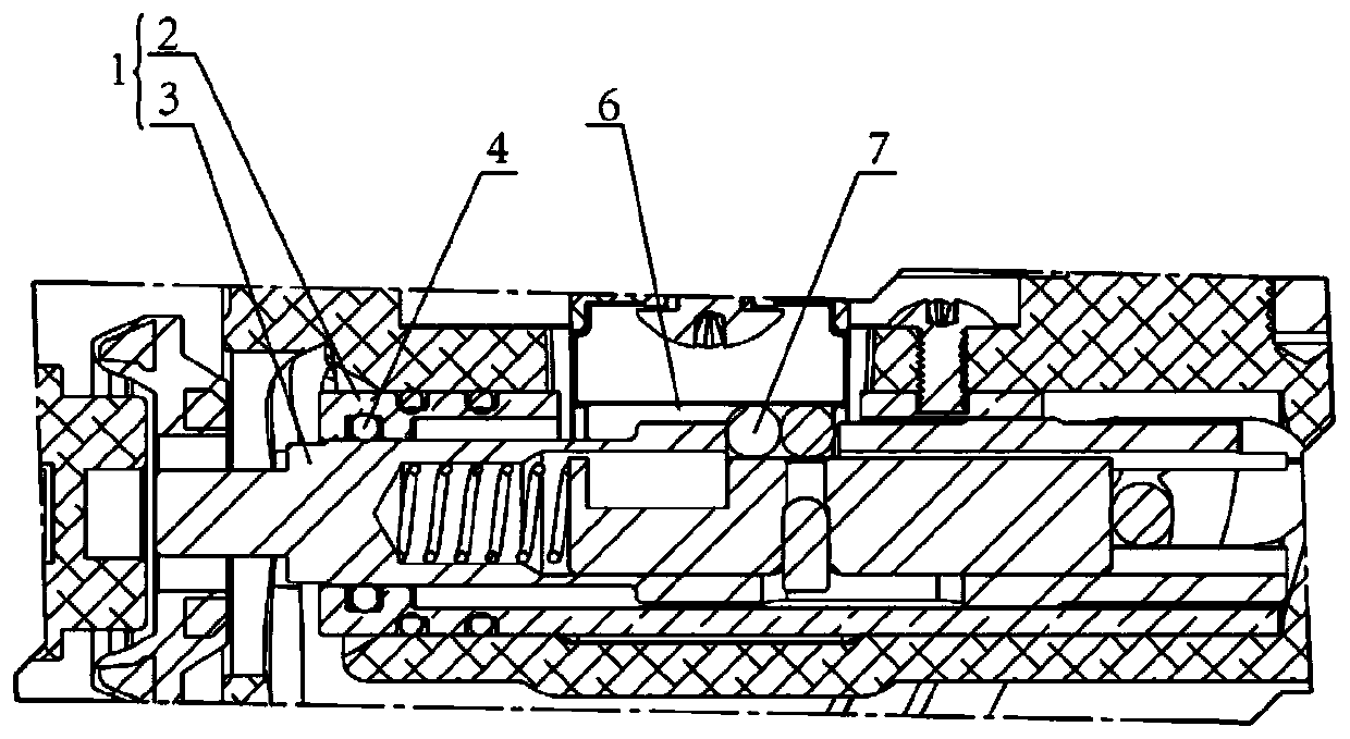
[0037] The first embodiment of the present invention provides a refueling gun 8 , including a switch shaft assembly 1 for controlling the opening or closing of the refueling gun 8 . see figure 1 , figure 2 and Image 6 As shown, the switch shaft assembly 1 includes an outer shaft 3 and an outer shaft sleeve 2 . Wherein, the outer shaft 3 can reciprocate in the outer shaft sleeve 2, which is characterized in that a rod-type seal is adopted between the outer shaft 3 and the outer shaft sleeve 2, and the outer shaft sleeve 2 includes an inner wall and an outer wall of the outer shaft 3. seals (not shown). The axis of the switch shaft assembly 1 and the axis of the main shaft are arranged on the same straight line.

[0038] By arranging the switch shaft assembly 1 and the main shaft on the same straight line, it can be ensured that the main shaft can be triggered when the switch shaft assembly 1 is working, so as to control the opening or closing of the oil gun 8 .

[0039] ...

Embodiment approach 2

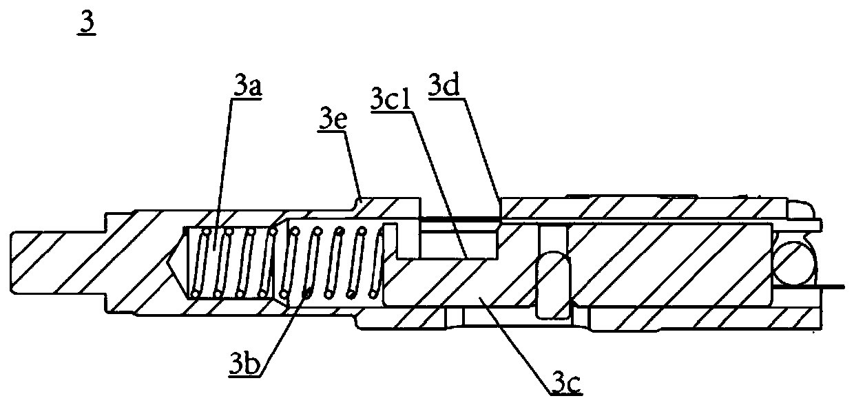
[0051] The second embodiment of the present invention provides a fuel gun 8, this embodiment is a further improvement on the first embodiment, the main improvement is that, in this embodiment, see figure 2 with image 3 As shown, the surface roughness of the outer wall of the outer shaft 3 is in the range of Ra0.2-Ra1.2.

[0052] The inventors of the present invention found that when the surface roughness of the outer side wall of the outer shaft 3 is greater than Ra1.2, the wear on the contact surface of the sealing ring 4 is very serious, which not only affects the use feel of the oil gun 8, but also seriously affects the sealing ring 4. service life. And when the surface roughness of the outer shaft 3 is less than Ra0.2, not only will the cost of machining the surface of the outer shaft 3 be greatly increased, but at the same time, because the surface of the outer shaft 3 is too smooth, the sealing ring 4 may adhere to the outer shaft 3, when the outer shaft 3 moves, it ...

Embodiment approach 3

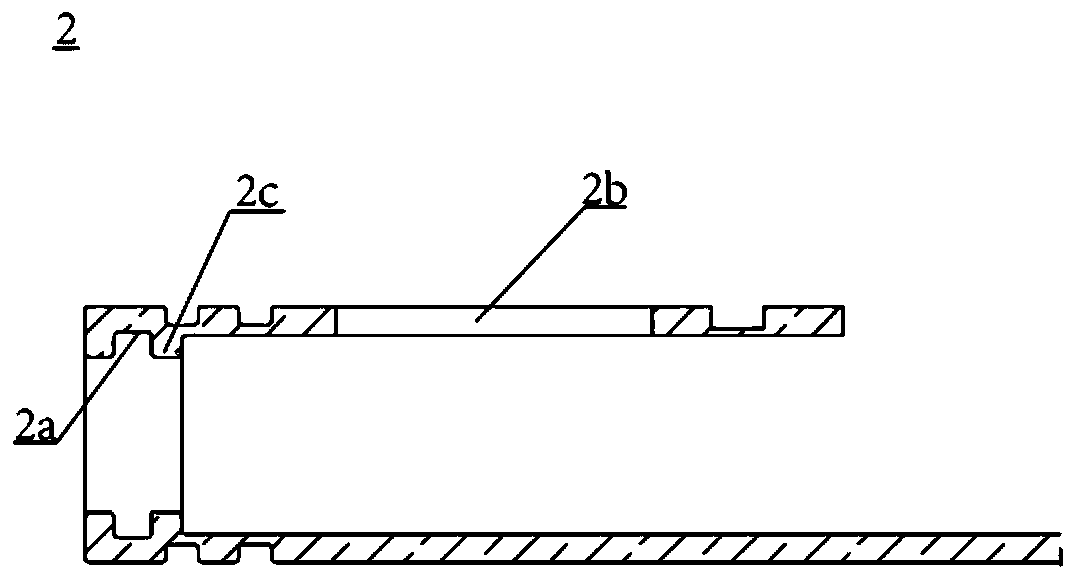
[0056] The third embodiment of the present invention provides a fuel gun 8. This embodiment is a further improvement on the first and second embodiments. The main improvement is that in this embodiment, see figure 1 with figure 2 As shown, a first boss portion 2c is formed on the outer wall of the outer shaft 3, and a second boss portion 3e is provided on the outer sleeve 2, and the first boss portion 2c can abut against the second boss portion 3e. .

[0057] Specifically, in this embodiment, one end of the outer shaft sleeve 2 is formed with a second boss portion 3e, wherein the second boss portion 3e extends inward from the inner wall of the outer shaft sleeve 2 and forms a ring shape, and the sealing groove 2a is arranged on the side wall of the second boss portion. Correspondingly, a first boss portion 2c capable of abutting against it is formed on the outer wall of the outer shaft 3, wherein the first boss portion 2c is formed by extending outward from the outer side o...


PUM


Abstract

The invention relates to the technical field of fuel filling and oil and gas recovery, in particular to a refueling gun and refueling equipment. The refueling gun comprises a switch shaft component connected with a spindle and a gas path valve component and used for controlling the refueling gun to be opened or closed; the switch shaft component comprises an outer shaft and an outer shaft sleeve;the outer shaft can reciprocate inside the outer shaft sleeve; the outer shaft sleeve comprises a sealing piece arranged between the inner wall of the outer shaft sleeve and the outer wall of the outer shaft; at least one sealing groove is formed in the inner wall of the outer shaft sleeve; and the sealing piece is embedded in the sealing groove. According to the refueling gun, the positions of the sealing piece and the sealing groove are changed, so that piston type sealing is changed into pull rod type sealing, the wear of the sealing piece and the frictional resistance to the sealing pieceare reduced, the service life of the sealing piece is effectively prolonged, and the hand feeling for use of the refueling gun is improved.

Description

technical field [0001] The invention relates to the technical field of fuel filling and oil gas recovery, in particular to a fueling gun and fueling equipment. Background technique [0002] At present, the oil and gas recovery technology is becoming more and more mature, but the self-sealing refueling gun, which is the terminal product of oil and gas recovery, generally has the disadvantages of complex assembly and processing technology and low reliability. Moreover, in order to ensure the sealing performance of the fuel gun, a plurality of sealing members need to be arranged in the fuel gun to seal the oil passage and the gas passage of the fuel gun, thereby improving the reliability of the fuel gun and ensuring the safety during use. [0003] Take the switch shaft assembly in the existing fuel gun as an example, the switch shaft assembly is connected with the vacuum cap assembly, controls the air circuit and the oil circuit at the same time, and operates through the trigge...

Claims


Application Information

Patent Timeline
Patent Type & Authority Applications(China)
IPC IPC(8): B67D7/50B67D7/52
Inventor 周学俊李华平
Owner 苏州三米格环保科技有限公司
Why Eureka
Try Eureka