
Semi-automatic device for combining bulk optical fibers at optical cable end socket into belt fiber and belt-combining method

A semi-automatic, optical fiber technology, applied in the field of optical fiber communication, can solve the problems of inappropriate fixtures and equipment, etc., and achieve the effect of simple structure and convenient operation

Pending Publication Date: 2019-05-10
SHANGHAI YONGYI PHOTOELECTRIC TECH CO LTD
View PDF0 Cites 0 Cited by
  • Summary
  • Abstract
  • Description
  • Claims
  • Application Information

AI Technical Summary

Problems solved by technology

[0003] However, some optical communication products can only combine very short loose fibers at the end of the optical cable into ribbon fibers, often only a few tens of millimeters or even a few millimeters shorter. At this time, it is not suitable to use large-scale automatic combining equipment , the use of jigs and equipment that combine fibers from one end to the other is not suitable

Method used


Image

  • Semi-automatic device for combining bulk optical fibers at optical cable end socket into belt fiber and belt-combining method
  • Semi-automatic device for combining bulk optical fibers at optical cable end socket into belt fiber and belt-combining method
  • Semi-automatic device for combining bulk optical fibers at optical cable end socket into belt fiber and belt-combining method

Examples


Embodiment Construction

[0031] Hereinafter, preferred embodiments of the present invention will be described with reference to the accompanying drawings. The drawings are provided for the purpose of illustrating the embodiments and are not intended to limit the scope of the invention. In the drawings, the same reference numerals denote the same components, and description thereof may not be repeated. The dimensional ratios of the drawings are not necessarily exact.

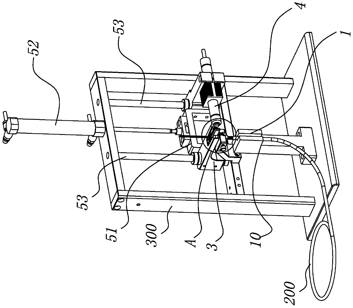
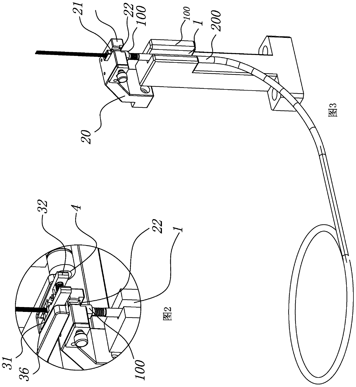
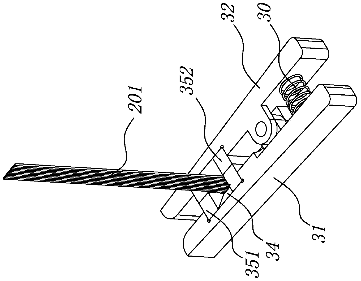
[0032] The invention provides a semi-automatic device for dispersing optical fibers at the end of an optical cable and forming a ribbon fiber, comprising an optical cable guiding and positioning component, a body fixing component, an optical fiber positioning, guiding and fixing component, a UV light source and a lifting component.

[0033] The optical cable guiding and positioning part 10 is installed on the fixing frame 300 of the device, and is located below the body fixing assembly, and is used for guiding and positioning the optica...


PUM


Abstract

The invention provides a semi-automatic device for combining bulk optical fibers at optical cable end socket into belt fiber and a belt-combining method. An optical cable guiding positioning part is located below of a body fixing module; the optical fiber positioning guiding fixing module is closely located above the body fixing module; the optical fiber positioning guiding fixing module comprisesan openable clamp for which the elastic component provides clamping force; openable and closable vertical parallel optical fiber limiting holes are arranged on the clamp, and a glue storage hopper isformed at the upper end orifices of the vertical parallel optical fiber limiting holes; a UV light source is close to the locations of the lower end orifices of the parallel optical fiber limiting holes; the optical fiber positioning guiding fixing module, the UV light source and a lifting module are connected and capable of synchronously lifting. The invention further provides a method for combining bulk optical fibers at optical cable end socket. The semi-automatic device disclosed by the invention is simple in structure, for the assembling connector containing 4, 8 or 12,24 optical cablesin several meters even several hundred meters, the ultrashort dispersed optical fibers exposed from the optical cable end socket need to be combined into the belt fiber, the operation is convenient, fast and accurate.

Description

technical field [0001] The invention relates to the technical field of optical fiber communication, in particular to a semi-automatic device and method for combining scattered optical fibers at the end of an optical cable into a ribbon. Background technique [0002] In optical communication products, when optical fiber is used as the media medium, long-distance optical cables are often used. In order to facilitate the fast connection between optical cables and between optical cables and devices, it is often necessary to assemble connectors at the ends of optical cables. Because the optical fiber in the optical cable is composed of 4-24 and more loose fibers, in order to facilitate the assembly of the connector, it is necessary to combine different numbers of loose fibers into ribbon fibers according to requirements. [0003] However, some optical communication products can only combine very short loose fibers at the end of the optical cable into ribbon fibers, often only a f...

Claims


Application Information

Patent Timeline
IPC IPC(8): G02B6/44
Inventor 张连军侯伟
Owner SHANGHAI YONGYI PHOTOELECTRIC TECH CO LTD
Learn More