
Barcode identifying and reading device

A barcode and equipment technology, applied in the field of barcode recognition, can solve the problems affecting user experience, code reading equipment cannot read and decode barcodes normally, and high image noise, so as to improve the ability to resist stray light interference, enhance the effect of blocking stray light, and avoid stray light. The effect of stray light entering the lens

Active Publication Date: 2019-05-10
福州符号信息科技有限公司
View PDF4 Cites 4 Cited by
  • Summary
  • Abstract
  • Description
  • Claims
  • Application Information

AI Technical Summary

Problems solved by technology

[0002]The barcode scanning methods of existing barcode recognition equipment are roughly divided into the following two types: 1. Active code scanning: the merchant holds a barcode scanner to scan the barcode presented by the user, In the process of scanning the code, it is necessary to manually hold the scanning gun and adjust the angle of the scanning gun so that the camera can capture a clear barcode image. However, this method must be manually scanned, which cannot meet the requirements of unmanned scanning in places such as toll stations and parking lots. Charge requirements; 2. Passive scanning code type: the barcode recognition device is fixed, and the user holds the mobile terminal, and the identification code on the mobile terminal is close to the lens of the barcode recognition device at a short distance, and adjusted at multiple angles Barcode, otherwise the reading success rate is low, affecting user experience
When the passive code scanning method is applied to unmanned toll collection management such as parking lots and toll stations, the following problems will arise: 1) The user must adjust the angle of the barcode multiple times, which takes a long time to scan the code and is likely to cause congestion; The barcode is close to or close to the camera at a relatively short distance
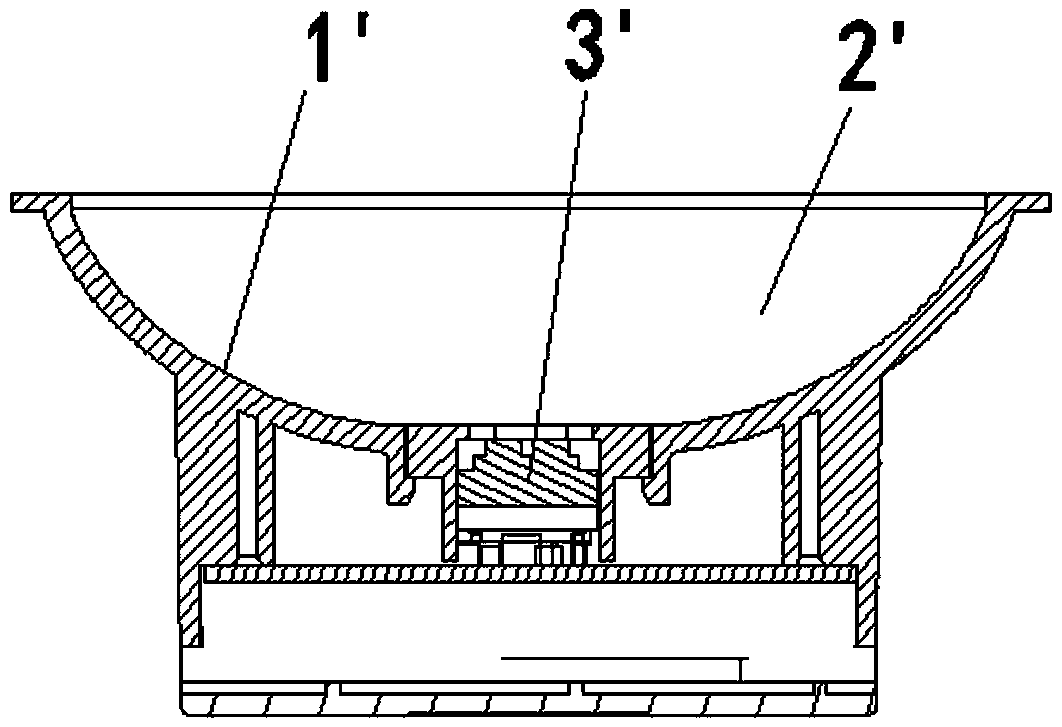
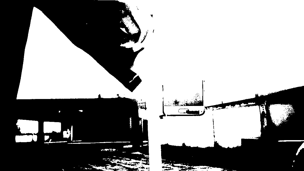
Existing fixed barcode recognition equipment (such as figure 1 As shown) it is impossible to obtain a clear and readable barcode image at a long distance. This is because the light incident on the lens of the existing fixed barcode recognition equipment is the light at any angle in front of the lens. When the application scans the code at a long distance, the incident The light contains a lot of external environmental stray light, for example, the specular light on the mobile terminal used to display the identification code, multi-angle astigmatism in natural light, and other high-brightness external lighting sources, etc. When barcodes are used, the barcode is close to or close to the lens to block a large area of ​​external environment stray light, and the interference caused is very small. The light has caused serious interference to the barcode image captured by the image sensor, so that the image noise in the captured image is too high, and the code reading equipment cannot normally read and decode the barcode, such as figure 2 as shown, figure 2 for adoption figure 1 The barcode reading device shown above scans the code at a long distance (the distance between the barcode and the reading device is 60cm) to obtain the barcode image

Method used


Image

  • Barcode identifying and reading device
  • Barcode identifying and reading device
  • Barcode identifying and reading device

Examples


Embodiment Construction

[0045] The present invention will be described in detail below in conjunction with the accompanying drawings and specific embodiments.

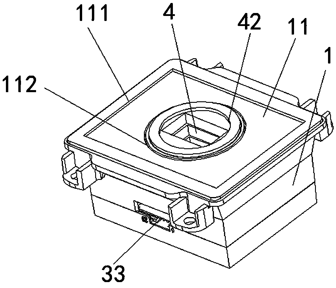
[0046] see Figure 3 to Figure 5 , a barcode reading device, comprising a housing 1, a slot-shaped slot-shaped viewing window 4 with openings 42 and 43 at both ends, and a camera module 2 and a circuit board 3 arranged in the housing 1, the housing 1 The front side 11 is provided with a hole 12, and the slot-type viewfinder 4 is sleeved in the hole 12; the depth value D of the slot-type viewfinder 4 is1 ≥10mm (see Figure 17 ), the lens 21 of the camera module 2 captures a barcode image through the slot-shaped viewfinder 4, and then transmits it to the processor 31 on the circuit board 3 for decoding to obtain barcode information. The barcode information can be transmitted externally through the data transmission interface 33 on the circuit board 3, or wirelessly transmitted externally through the wireless communication module. The deep slo...


PUM


Abstract

The bar code reading device comprises a shell, a groove-shaped view finding window with openings in the two ends, a camera module and a circuit board, the camera module and the circuit board are arranged in the shell, a hole is formed in the front face of the shell, and the groove-shaped view finding window is arranged in the hole in a sleeved mode; wherein the depth value D1 of the groove-shapedview finding window is greater than or equal to 10 mm, and the lens of the camera module collects a bar code image through the groove-shaped view finding window and then transmits the bar code image to a processor on the circuit board for decoding to obtain bar code information. According to the bar code identifying and reading device, through the deep groove-shaped view finding window and the fluctuation arranged on the side wall of the groove-shaped view finding window, stray light is effectively prevented from entering the lens, and therefore a clear bar code image is captured in a long distance.

Description

technical field [0001] The invention relates to a barcode reading device, which belongs to the field of barcode identification. Background technique [0002] The barcode scanning methods of existing barcode recognition equipment are roughly divided into the following two types: 1. Active code scanning: the merchant holds a barcode scanner to scan the barcode presented by the user. The angle of the gun enables the camera to capture a clear barcode image, but this method must be manually scanned, which cannot meet the needs of unmanned scanning codes such as toll stations, parking lots, etc.; 2. Passive code scanning: the barcode recognition device is fixed Manually, the user holds the mobile terminal, closes the identification code on the mobile terminal or approaches the lens of the barcode reading device at a relatively short distance, and adjusts the barcode from multiple angles. Otherwise, the success rate of reading is low and affects the user experience. When the passi...

Claims


Application Information

Patent Timeline
Patent Type & Authority Applications(China)
IPC IPC(8): G06K7/10
Inventor 吴文彬
Owner 福州符号信息科技有限公司
Learn More