
Polishing device

A grinding mechanism, No. 1 technology, which is applied to grinding drive devices, grinding automatic control devices, grinding/polishing safety devices, etc., can solve the problems that the cutting mechanism is not very useful, occupies usable area, and reduces work efficiency, etc. Achieve the effect of fast grinding speed, low maintenance cost and high cutting efficiency

Active Publication Date: 2019-05-14
诸暨市凯贝乐科技有限公司
View PDF6 Cites 0 Cited by
  • Summary
  • Abstract
  • Description
  • Claims
  • Application Information

AI Technical Summary

Problems solved by technology

[0004] However, in the prior art and patent No. CN201610519554, in addition to the grinding mechanism, a cutting mechanism is also included. If the cut wood is polished, the cutting mechanism is not very useful, and the use area will be occupied, and the device will be enlarged. Volume, when the staff operates the mobile device, it is inconvenient to use, difficult to move, and reduces work efficiency. At the same time, the grinding mechanism is grasped by the manipulator. If it is not careful, it will cause damage to the wood. Although the existing grinding device is powerful, it is bulky The maintenance cost is high, and although some small grinding devices are practical, they cannot liberate manpower very well. In order to meet the market demand, it is very necessary to design a wood grinding device

Method used


Image

  • Polishing device
  • Polishing device
  • Polishing device

Examples


Embodiment Construction

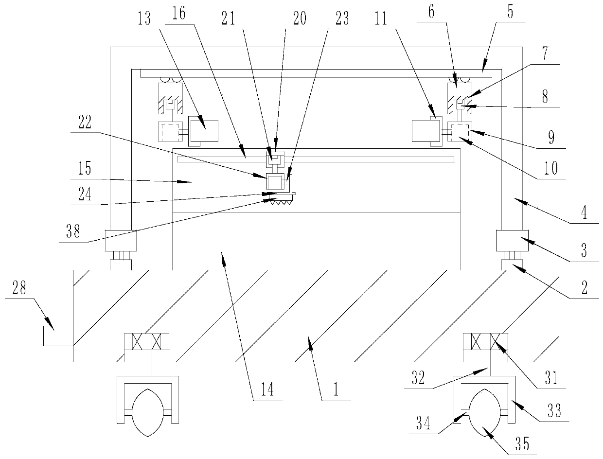
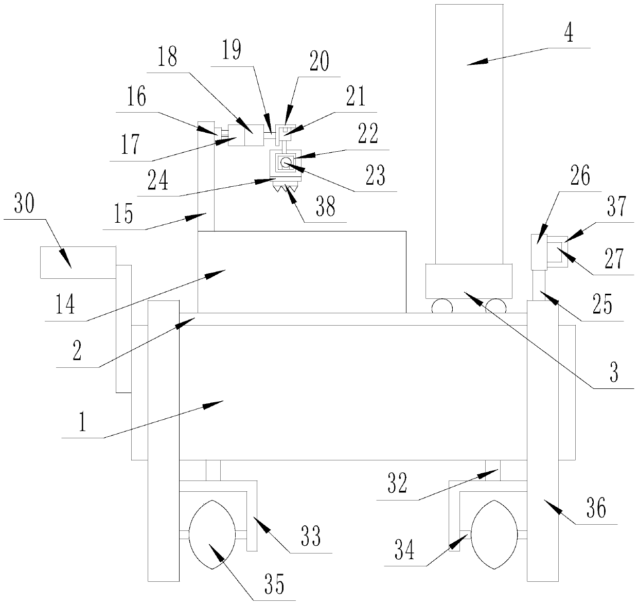
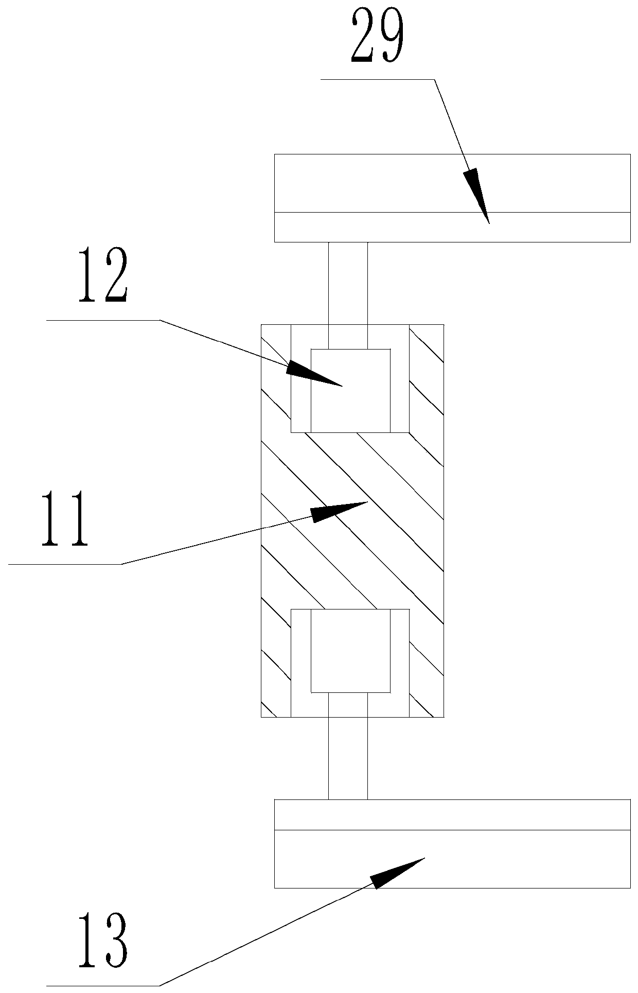
[0023] The present invention is specifically described below in conjunction with accompanying drawing, as Figure 1-5As shown, a kind of grinding device comprises bearing plate 1, and the upper surface of described bearing plate 1 is provided with grinding mechanism, and described grinding mechanism is arranged on each The No. 1 electric trolley 3 on the No. 1 slide rail 2, the portal frame 4 arranged on the upper surface of a group of No. 1 electric trolley 3, the No. 2 slide rail 5 arranged on the lower surface of the portal frame 4 beam, and the No. A group of No. 2 electric trolleys 6 on the slide rail 5, a No. 1 mounting block 7 arranged on the lower surface of each No. 2 electric trolley 6, and a No. 1 circular recess processed at the center of each No. 1 mounting block 7 lower surface. Groove, the hydraulic cylinder 8 that is arranged in each No. 1 circular groove and the telescopic end is downward, the No. 1 mouth-shaped mounting frame 9 that is arranged on the telesco...


PUM


Abstract

The invention discloses a polishing device. The polishing device comprises a bearing plate. A polishing mechanism is arranged on the upper surface of the bearing plate. A vertical rod is arranged on the upper surface of the bearing plate and is located in front of a storage table. A second vertical mounting plate is arranged on the upper surface of the vertical rod. A controller is arranged on thefront surface of the second vertical mounting plate. A mains supply interface is arranged on the side surface of the bearing plate. A supply terminal of the controller is connected with the mains supply interface through a wire. The output end of the controller is connected with a first electric trolley, a second electric trolley, a hydraulic cylinder, a rotary motor, a first micro linear motor,a third electric trolley, an electric push rod, a micro hydraulic cylinder and a second micro linear motor through wires. The polishing device has the beneficial effects that semi-automatic stationaryor rotatable polishing is adopted, so that the polishing speed is high, manpower is liberated, the working efficiency is improved, the size is moderate, moving is convenient and fast, using is convenient, and the novelty is high.

Description

technical field [0001] The invention relates to the field of grinding, in particular to a grinding device. Background technique [0002] With the development of society and the improvement of people's living standards, people's demand for resources also increases. Timber is an indispensable resource in people's daily life and construction. The second grinding removes the burrs and protrusions on the wood, which is convenient for later processing. Manual grinding is time-consuming and laborious, and the grinding surface needs to be turned over, so the work efficiency is slow. Although the existing grinding device is powerful, it is bulky and expensive to maintain. , and although some small grinding devices are practical, they cannot liberate manpower well. In order to meet market demand, it is very necessary to design a grinding device. [0003] The existing patent CN201610519554 discloses a patent named a wood cutting and grinding device. The patent uses a manipulator to pi...

Claims


Application Information

Patent Timeline
Patent Type & Authority Applications(China)
IPC IPC(8): B24B27/00B24B41/02B24B19/24B24B41/06B24B47/08B24B55/00
CPCB24B7/075B24B7/28B24B9/18B24B41/00B24B41/005B24B41/02B24B47/02B24B51/00
Inventor 华巧波
Owner 诸暨市凯贝乐科技有限公司
Learn More