Compound needle for flat knitting machine

A compound needle and flat knitting technology applied to compound needles. It can solve the problems of high processing accuracy of the main needle and needle cover, complex main needle structure, affecting the knitting effect, etc., and achieve the effect of simple and neat transfer action, improved fabric quality, and improved production efficiency.

Active Publication Date: 2019-05-14
NINGBO CIXING
View PDF7 Cites 2 Cited by
  • Summary
  • Abstract
  • Description
  • Claims
  • Application Information

AI Technical Summary

Problems solved by technology

However, the structure of the main needle is too complicated, and the processing accuracy of the main needle and the needle sleeve is high.
At the same time, the top angle of the needle sleeve is inclined towards the main needle, so that when the top angle closes the needle hook, the width of the closed part increases, so that the passed loop becomes larger, which affects the knitting effect

Method used


Image

  • Compound needle for flat knitting machine
  • Compound needle for flat knitting machine
  • Compound needle for flat knitting machine

Examples


Embodiment 1

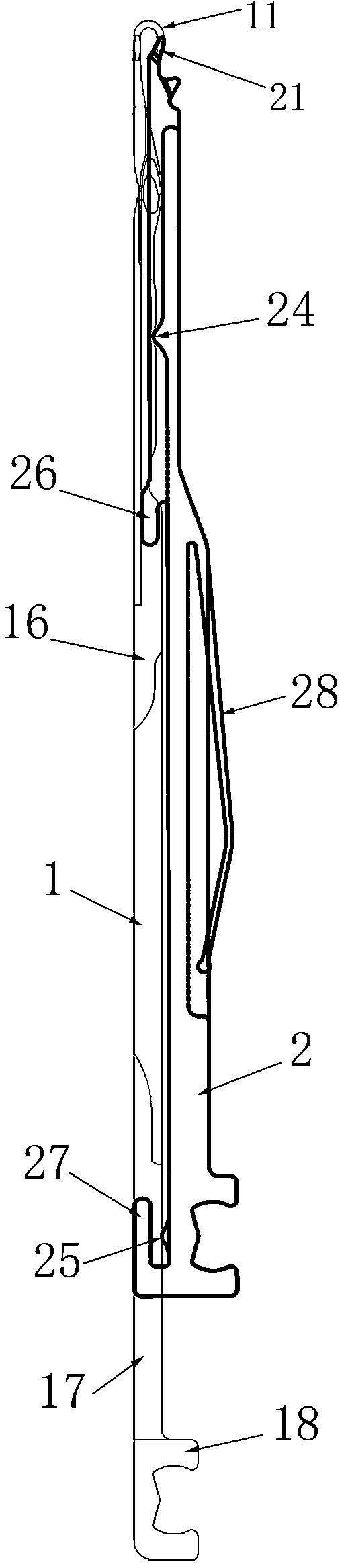
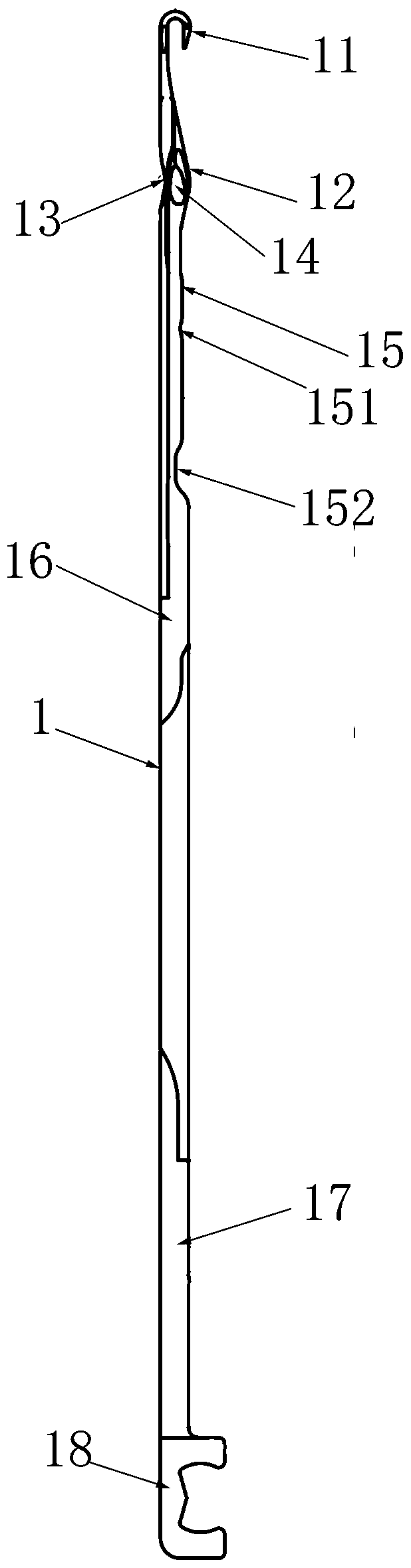
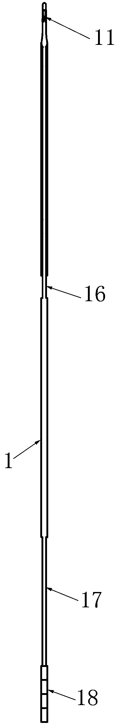
[0038]See attached picture. The compound needle described in this embodiment includes a main needle 1 and a needle sheath 2 fitted on the main needle; the main needle 1 is elongated and has a needle hook 11 on the head, and the bending direction of the needle hook is now defined as On the right side, the opposite direction of the needle hook bending is defined as the left side, and the two planes of the main needle are defined as the front and rear sides; under the needle hook, there is an outwardly protruding boss 12 on the right side of the main needle, opposite to it The left side of the main needle bends inwardly to form a concave avoidance groove 13, so that the size of the coil sliding range on the main needle is kept within a certain range, which is convenient for the movement of the coil on the main needle; the front and rear sides of the boss are provided with There is a recessed accommodating groove 14 for placing the top corner of the needle cover.

[0039] Boss 12...

Embodiment 2

[0048] The compound needle described in this embodiment includes a main needle and a needle cover set on the main needle; a protruding boss is provided on the right side of the main needle, and a concave accommodation groove is provided on the front and rear sides of the boss for use to place the top corner of the socket. There are convex points on the side of the convex platform extending downward, and the side of the needle sleeve facing the main needle is provided with an undulating track surface. The track surface is composed of a plurality of smooth concave-convex surfaces. The upper and lower track surfaces are in contact with each other, and two convex points can be set on the main needle. The two convex points are used to support the sliding of the needle sleeve under pressure, which reduces the contact area, thereby reducing the friction force and facilitating the needle sleeve. Smooth sliding in the needle groove. The track surface of the needle cover is located on ...


PUM


Abstract

The invention discloses a compound needle for a flat knitting machine. The compound needle comprises a main needle and a needle sleeve mounted on the main needle in a sleeving mode; the main needle isin a long and thin shape, and a needle hook is arranged at the head of the main needle; a top corner is arranged at the top end of the needle sleeve, the side, facing the main needle, of the needlesleeve is of an open groove structure, the front side face and the rear side face of the main needle are sunken inwards to form concave faces, and the needle sleeve is clamped onto the concave faces of the main needle through an open groove; and a salient point is arranged on one of the side face, facing the needle sleeve, of the main needle and the side face, facing the main needle, of the needlesleeve, a track face is arranged on the other one of the side face, facing the needle sleeve, of the main needle and the side face, facing the main needle, of the needle sleeve, the salient point ismatched with the track face, and thus when the needle sleeve moves, the top corner moves to the needle hook for closing the main needle from an accommodating groove of the main needle. The compound needle is small in knockover resistance, small in knockover stroke and high in weaving speed; a knitting needle at the relative position can be guided to enter the needle overturning position, needle overturning is reliable, and the action is simple; and the compound needle smoothly slides in a needle groove, and a cloth cover is flat.

Description

technical field [0001] The invention belongs to the technical field of knitting machinery, in particular to a compound needle used for flat knitting machines. Background technique [0002] At present, the use of compound needles on flat knitting machines is becoming more and more common. Better actions can be achieved through the mutual cooperation of various components in the compound needles, but the structure is complex, which increases the processing difficulty to a certain extent, increases the scrap rate, and increases Cost of production. The latch needle in the prior art has a rotatable latch on the needle bar. Through the opening and closing of the latch, it cooperates with the main needle and the yarn to complete the loop forming, stripping, tucking and unlooping of the loop latch. , transfer, stitching and other actions, because the latch rotation requires space, the main needle transfer is provided with a reed, so that this kind of needle needs a large up and dow...

Claims


Application Information

Patent Timeline
Patent Type & Authority Applications(China)
IPC IPC(8): D04B35/06
CPCD04B35/06
Inventor 孙平范徐卫东李立军克里斯托夫.吕蒂胡跃勇邹礼成
Owner NINGBO CIXING
Why Eureka
Try Eureka