Negative stiffness element with automatic balance position adjusting capacity and negative stiffness property generation method and application

An automatic adjustment and balance position technology, applied in modal testing, ultra-low frequency vibration isolation, gravity environment ground simulation, low frequency field, can solve the problems that cannot be effectively realized, the total displacement of the load quality change system exceeds the limit, etc.

Active Publication Date: 2019-05-14
HARBIN INST OF TECH
View PDF6 Cites 9 Cited by
  • Summary
  • Abstract
  • Description
  • Claims
  • Application Information

AI Technical Summary

Problems solved by technology

In order to ensure that the system has a low dynamic natural frequency, it often leads to excessive changes in the load mass during the static loading process of the system and the total displacement of the system exceeds the limit, while the mechanical characteristics of the static equilibrium position of the quasi-zero stiffness system are always based on the load mass of the system. Therefore, it is impossible to effectively realize the low natural frequency support (suspension) system with variable mass load under the premise of specific displacement limit
The prior art does not provide corresponding technical solutions for solving such technical contradictions

Method used


Image

  • Negative stiffness element with automatic balance position adjusting capacity and negative stiffness property generation method and application
  • Negative stiffness element with automatic balance position adjusting capacity and negative stiffness property generation method and application
  • Negative stiffness element with automatic balance position adjusting capacity and negative stiffness property generation method and application

Examples


specific Embodiment approach 1

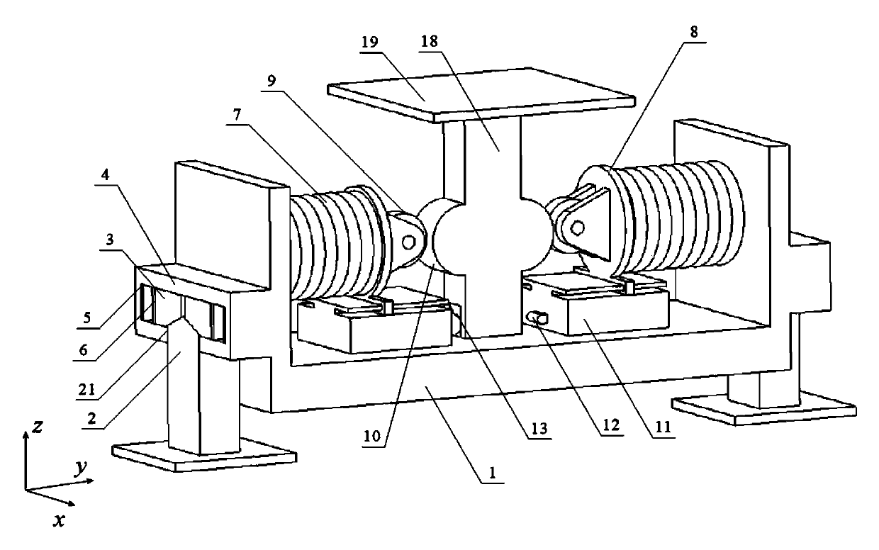
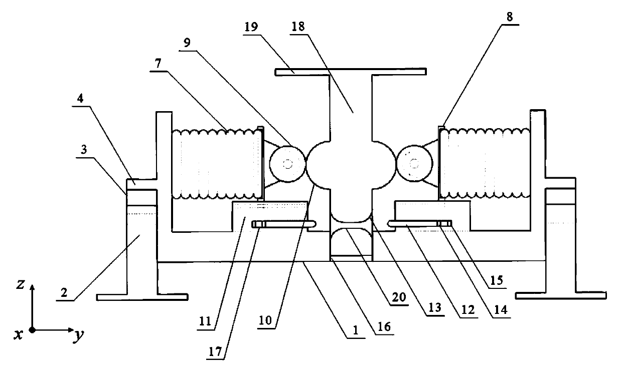
[0036] Specific implementation mode one: as figure 1 and 2 As shown, the negative stiffness element described in this embodiment includes a device housing 1, two wedge-shaped columns 2, four wedge-shaped sliders 3, two outer slideways 4, four wedge electromagnets 5, and four wedge permanent magnets 6 , two horizontal springs 7, two roller supports 8, two rollers 9, two arc surfaces 10, two roller slide rails 11, two bolts 12, two bolt arc surfaces 13, two bolt permanent magnets 14 , two bolt electromagnets 15, a column guide rail 16, two bolt slideways 17, a central column 18, a carrying platform 19, a bolt channel 20 and a wedge-shaped column slideway 21.

[0037] The outer end of the horizontal spring 7 is fixedly connected to the side wall of the device casing 1; the inner end surface of the horizontal spring 7 is fixedly connected to the roller support 8; the roller slide rail 11 is fixedly connected to the top of the device casing 1; the roller support 8 and the roller s...


PUM


Abstract

The invention provides a negative stiffness element with automatic balance position adjusting capacity and a negative stiffness property generation method and application, and relates to the field ofground-based simulation of gravity environment. The negative stiffness element with automatic balance position adjusting capacity and the negative stiffness property generation method and applicationare purposed to solve the problem of variation of mechanical property, caused by variable mass load, of a balance position of an existing high static and low dynamic stiffness supporting system; the dynamic stiffness of the new system is reduced on the premise that the original system balance position is not influenced so as to ensure that the stable balance position of the system in static loading process is the same as that of an original system; when dynamic load acts on the system, the system stiffness is the value of difference between the original system stiffness and the negative stiffness element stiffness. The geometric nonlinear property and adjustable geometric parameter property of a mechanism are utilized, the transverse spring stiffness and the effective length of a roller mechanism are properly set to realize the special negative stiffness property; a mechanism housing and a central vertical column are locked and unlocked to realize the negative stiffness property of opening and closing elements in a special condition. Therefore, the problems that the static displacement beyond the limit due to excessively low system stiffness or the mechanical property of a balancepoint of a quasi-zero stiffness system is damaged due to excessively low system stiffness can be avoided.

Description

technical field [0001] The invention relates to a negative stiffness element and a negative stiffness characteristic generation method and application, and relates to the fields of ground simulation in a gravity environment, low frequency, ultra-low frequency (zero frequency) vibration isolation, modal testing, and the like. Background technique [0002] In actual engineering, there is a large demand for support (suspension) systems with specific static support stiffness and low (zero) dynamic stiffness, such as space zero (micro) gravity simulation experiments, high-precision vibration isolation platforms, and large-scale flexible system modal test experiments, etc. . In recent years, a class of quasi-zero stiffness vibration isolation systems with high static stiffness and low dynamic stiffness has emerged, and its dimensionless dynamic equation can be summarized as m and k are the load mass and support stiffness, respectively. The system effectively reduces its natural...

Claims


Application Information

Patent Timeline
Patent Type & Authority Applications(China)
IPC IPC(8): F16F15/02
Inventor 曹庆杰朱光楠徐超刘吉晔张潇汉杨涛
Owner HARBIN INST OF TECH
Why Eureka
Try Eureka