High-efficiency balanced heating type hot gas generating barrel container

A heating-type, high-efficiency technology, applied in lighting and heating equipment, steam generation, firebox-type steam boilers, etc., can solve problems such as waste of resources, low heating efficiency, and large amounts of exhaust gas, and achieve increased heating and combustion surface, Effect of preventing gas unevenness and increasing discharge volume

Inactive Publication Date: 2019-05-14
周小辉
View PDF0 Cites 0 Cited by
  • Summary
  • Abstract
  • Description
  • Claims
  • Application Information

AI Technical Summary

Problems solved by technology

[0002] At present, the inner tank of the steam barrel in the prior art has problems such as the combustion area of ​​the gas in the combustion chamber is limited, and the flame and heat generated by the gas cannot be circulated in the combustion heating device, which not only wastes resources, but also produces a large amount of waste gas. polluted environment
[0003] At the same time, most of the inner tanks of the steam barrels in the prior art are composed of a combustion chamber and a heat exchange tube, and the combustion chamber and the inner tank are of a separate structure. The flame produced by the burner can only be burned in the combustion chamber, and the heat exchange tube is almost Can not touch the flame, the inner tank can only be heated at the bottom
This leads to problems such as combustion and heating efficiency are not high

Method used


Image

  • High-efficiency balanced heating type hot gas generating barrel container

Examples


Embodiment Construction

[0033] In order to make the object, technical solution and advantages of the present invention clearer, the present invention will be further described in detail below in conjunction with the accompanying drawings and embodiments.

[0034] It should be understood that the specific embodiments described here are only used to explain the present invention, not to limit the present invention.

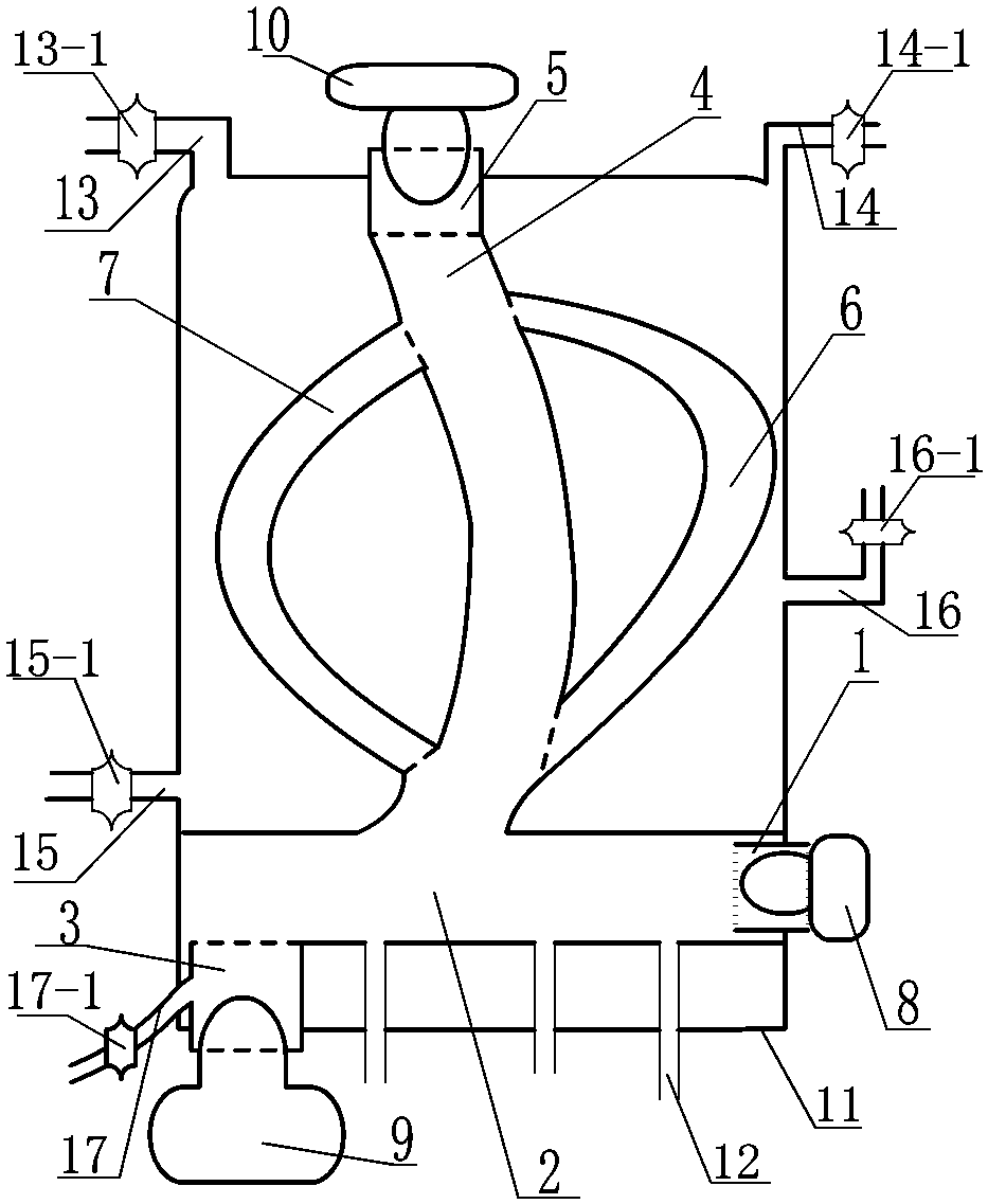
[0035] like figure 1 As shown, the present invention includes fan cylinder one 1, combustion chamber 2, combustion cylinder 3, main heating pipe 4, fan cylinder two 5, arc tube one 6, arc tube two 7, inner tank body 11, wherein, the The inner tank body 11 is a cylindrical body with a hollow structure, and the combustion chamber 2 is a cylindrical body with a hollow structure. The inner wall is sealed and welded.

[0036] In each embodiment, preferably, the fan barrel 1 is horizontally arranged on the right end of the combustion chamber 2 through the inner tank body 11, and the fan barrel...


PUM


Abstract

The invention discloses a high-efficiency balanced heating type hot gas generating barrel container. A combustion chamber is horizontally arranged on the lower portion in an inner container body, andthe outer wall of the combustion chamber and the inner wall of the inner container body are welded in a sealed manner; a first draught fan barrel penetrates through the inner container body to be horizontally arranged at the right end of the combustion chamber, and the first draught fan barrel communicates with the combustion chamber; a combustion barrel penetrates through the inner container bodyto be vertically arranged on the bottom face of the left portion of the combustion chamber, and the combustion barrel communicates with the combustion chamber; a main heating pipe is vertically arranged on the middle portion of the upper face of the combustion chamber, and the main heating pipe communicates with the combustion chamber; the main heating pipe is located on the middle portion in theinner container body; a second draught fan barrel penetrates through the inner container body to be vertically arranged on the middle portion of the upper end of the main heating pipe, and the seconddraught fan barrel communicates with the main heating pipe; a first arc-shaped pipe is arranged on the right side of the main heating pipe, and the first arc-shaped pipe communicates with the main heating pipe; and a second arc-shaped pipe is arranged on the left side of the main heating pipe, and the second arc-shaped pipe communicates with the main heating pipe.

Description

technical field [0001] The invention relates to the technology of burning and heating steam tank liners, in particular to the field of high-efficiency balanced heating type hot gas generating tank tanks. Background technique [0002] At present, the inner tank of the steam barrel in the prior art has problems such as the combustion area of ​​the gas in the combustion chamber is limited, and the flame and heat generated by the gas cannot be circulated in the combustion heating device, which wastes resources and produces a large amount of waste gas. polluted environment. [0003] At the same time, most of the inner tanks of the steam barrels in the prior art are composed of a combustion chamber and a heat exchange tube, and the combustion chamber and the inner tank are of a separate structure. The flame produced by the burner can only be burned in the combustion chamber, and the heat exchange tube is almost Can't touch flame, just can only burn and heat at the bottom in the l...

Claims


Application Information

Patent Timeline
Patent Type & Authority Applications(China)
IPC IPC(8): F22B13/02F22B13/14F22B37/06F22B37/48
Inventor 周小辉
Owner 周小辉
Why Eureka
Try Eureka