Calibration method, device and system for a pipeline measuring robot
A technology for measuring robots and calibration methods, which is applied in the calibration field of pipeline three-dimensional measurement robots, can solve problems such as difficult calibration of three-dimensional attitude deviation, and achieve the effect of reducing friction
- Summary
- Abstract
- Description
- Claims
- Application Information
AI Technical Summary
Problems solved by technology
Method used
Image
Examples
Embodiment 1
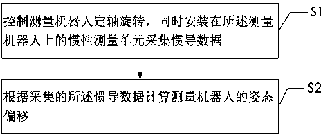
[0038] The first embodiment provided by the present invention is a calibration method for a pipeline measuring robot, such as figure 1 As shown, the calibration method includes:
[0039] Step S1. Control the measuring robot to rotate with a fixed axis, and at the same time, the inertial measurement unit installed on the measuring robot collects inertial navigation data.
[0040] In this step, the measuring robot is erected on the calibration device, and the measuring robot is controlled to rotate with a fixed axis. The calibration device used in this step can be a device capable of elevating the pipeline measurement robot, and the device can only have a support for the measurement robot, and a base for fixing the support, or it can be a device with two fixed The stand realizes the means for elevating the measuring robot.
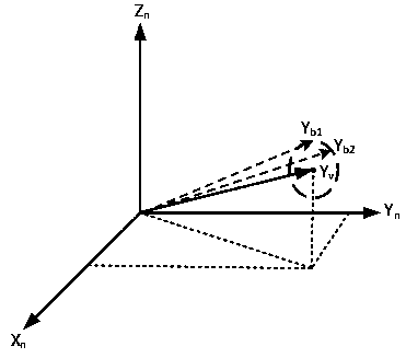
[0041] After the measuring robot is elevated, control the measuring robot to rotate with a fixed axis. Since an inertial measurement unit is installed in...
Embodiment 2
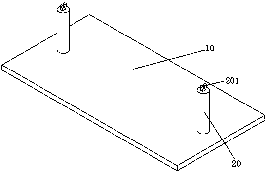
[0085] The second embodiment provided by the present invention is a calibration device for a pipeline measuring robot, such as image 3 As shown, it is used to measure and calibrate the measuring robot, combined with Figure 4 , the measurement robot includes: an electronic warehouse 301 with an inertial measurement unit installed inside, a sliding bar 303 symmetrically arranged on both sides of the electronic warehouse 301, and a walking wheel 302 evenly arranged on the sliding bar 303;
[0086] The calibration device includes:
[0087] A base 10, a bracket 20 arranged on the base 10;
[0088] The bracket includes: a left bracket and a right bracket;
[0089] The upper ends of the left bracket and the right bracket are both provided with a V-shaped bracket 201 , one end of the slide bar 303 is connected to the center of both sides of the electronic compartment, and the other end is erected on the V-shaped bracket 201 .
[0090] Optionally, the structures of the left bracke...
Embodiment 3
[0095] The third embodiment provided by the present invention is a calibration system for a pipeline measuring robot, which combines image 3 and Figure 4 As shown, the system includes: a pipeline measurement robot and a calibration device;
[0096]The measuring robot includes: the measuring robot includes: an electronic cabin with an inertial measurement unit installed inside, sliding bars symmetrically arranged on both sides of the electronic box, and walking wheels evenly arranged on the sliding bars;
[0097] The calibration device includes: a base, a bracket arranged on the base;
[0098] The bracket includes: a left bracket and a right bracket;
[0099] The upper ends of the left bracket and the right bracket are both provided with V-shaped brackets, one end of the slide bar is connected to the center of both sides of the electronic warehouse, and the other end is erected on the V-shaped bracket.
[0100] Preferably, the left bracket and the right bracket are arrange...
PUM
 Abstract
Description
Claims
Application Information
 - R&D
- Intellectual Property
- Life Sciences
- Materials
- Tech Scout
- Unparalleled Data Quality
- Higher Quality Content
- 60% Fewer Hallucinations
Browse by: Latest US Patents, China's latest patents, Technical Efficacy Thesaurus, Application Domain, Technology Topic, Popular Technical Reports.
© 2025 PatSnap. All rights reserved.Legal|Privacy policy|Modern Slavery Act Transparency Statement|Sitemap|About US| Contact US: help@patsnap.com


