
Current transformer under closed loop feedback control

A current transformer and closed-loop feedback technology, applied in the direction of voltage/current isolation, etc., can solve the problem of low reliability of optical fiber current transformer detection

Pending Publication Date: 2019-05-14
XUJI GRP +1
View PDF0 Cites 2 Cited by
  • Summary
  • Abstract
  • Description
  • Claims
  • Application Information

AI Technical Summary

Problems solved by technology

[0004] The purpose of the present invention is to provide a current transformer with closed-loop feedback control to solve the problem of low detection reliability of existing optical fiber current transformers

Method used


Image

  • Current transformer under closed loop feedback control
  • Current transformer under closed loop feedback control
  • Current transformer under closed loop feedback control

Examples


Embodiment Construction

[0014] The present invention will be described in further detail below in conjunction with the accompanying drawings.

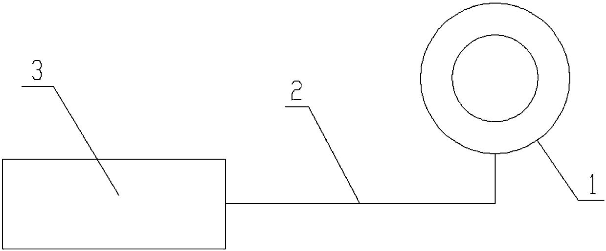
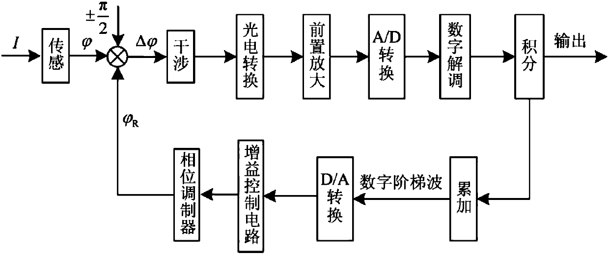
[0015] The optical fiber current transformer provided in this embodiment has a closed-loop feedback control function. Such as figure 1 As shown, it includes three parts: an all-fiber sensing ring 1 , a polarization-maintaining fiber 2 and a collector 3 . The all-fiber sensing ring 1 mainly completes the transmission and transformation of the primary current, outputs polarization information light, and transmits it to the collector 3 through the polarization-maintaining optical fiber 2 for signal processing, and outputs a digital quantity proportional to the magnitude of the primary current while generating a modulation signal and feedback control The signal performs high-speed closed-loop feedback control on the all-fiber sensing system.

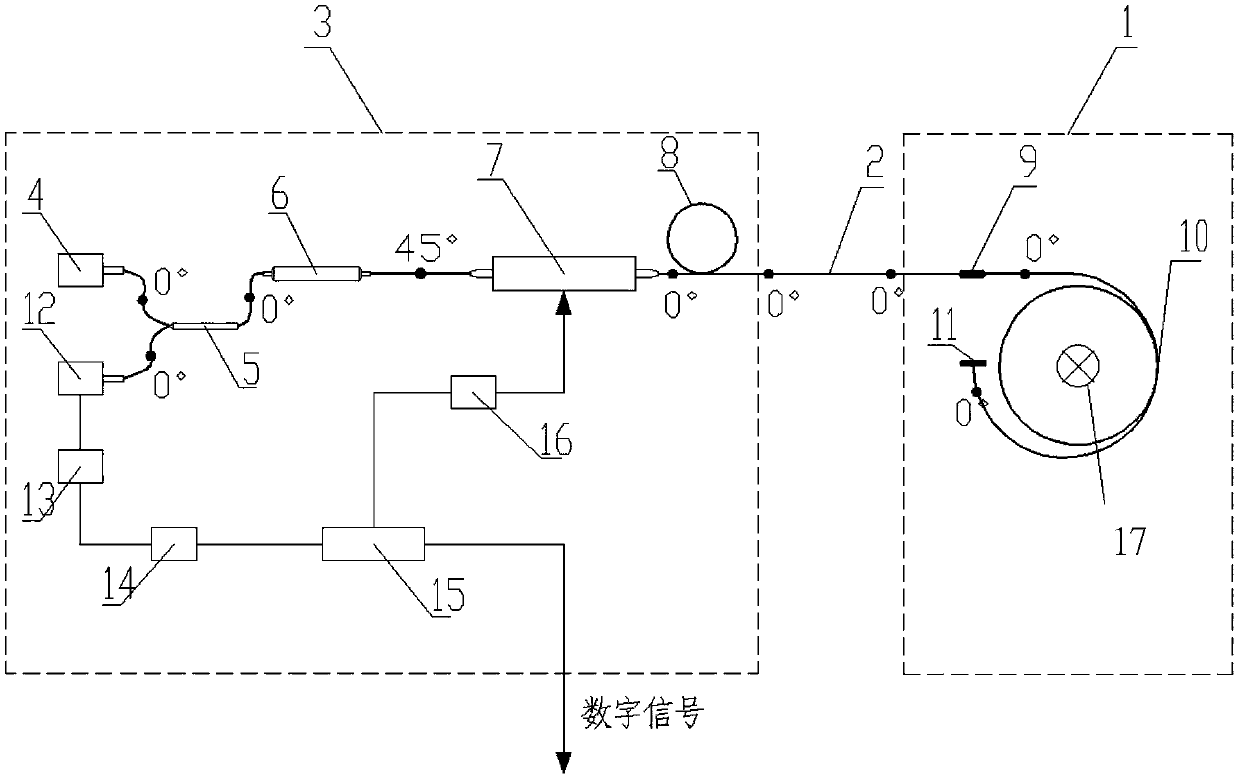
[0016] Such as figure 2 As shown, the collector 3 includes a light source 4, a fiber coupler 5, a fiber polarizer 6, ...


PUM


Abstract

The invention relates to a current transformer under closed loop feedback control. The current transformer comprises a full optical fiber sensing ring 1, a polarization maintaining optical fiber 2 anda collector 3; the collector 3 comprises a light source 4, an optical fiber coupler 5, an optical fiber polarizer 6, a straight waveguide phase modulator 7, a polarization optical fiber delay ring 8,a photoelectric detector 12, a signal conditioning circuit 13, an A / D converter 14, a processing module 15 and a D / A converter 16; the full optical fiber sensing ring 1 comprises an optical fiber wave plate 9, a circular-preservation sensing optical fiber 10 and an optical fiber reflector 11. The feedback control can be performed on a phase state of the sensing optical path through a closed-loopfeedback ring formed by the photoelectric detector 12, the signal conditioning circuit 13, the A / D converter 14, the processing module 15 and the D / A converter 16. Therefore, through the cooperative use of various components in the current transformer and the closed-loop feedback control, the detection reliability of the optical fiber current transformer can be improved, and the high-reliability detection can be realized.

Description

technical field [0001] The invention relates to a current transformer with closed-loop feedback control. Background technique [0002] The flexible DC grid system is very different from the AC system. The fault has its own characteristics, which are mainly reflected in the following aspects: 1) The fault current rises rapidly; 2) The scope of influence is wide; 3) The fault location is difficult; 4) DC disconnection The technical difficulty of the equipment is high; 5) Various power electronic units interact with each other. The flexible DC system needs to adopt high-speed digital measurement technology, which requires high response time, dynamic range, and precision of the measurement system. New key technologies and equipment for high-speed measurement suitable for high-voltage and large-capacity flexible DC need to be studied urgently. [0003] With the high-speed operation of the DC circuit breaker and the protection of the converter valve control device in the flexible...

Claims


Application Information

Patent Timeline
IPC IPC(8): G01R15/24
Inventor 袁亮韩笑步梦琼翟鹏飞刘万成李文明范冬冬李宝明
Owner XUJI GRP
Learn More