Excitation regulator trigger pulse detection method, device, detector and test fixture

An excitation regulator and trigger pulse technology, which is applied in the field of power electronics, can solve problems such as abnormal function of the excitation regulator, abnormal control of the excitation current, and the inability to know the function status of the excitation regulator.

Active Publication Date: 2021-05-04
HNAC TECH
View PDF4 Cites 0 Cited by
  • Summary
  • Abstract
  • Description
  • Claims
  • Application Information

AI Technical Summary

Problems solved by technology

[0003] However, in the actual working process of the excitation system, the excitation regulator may function abnormally due to the interference of various factors, such as not outputting the trigger pulse, or the phase of the trigger pulse is abnormal
Users generally cannot know the function status of the excitation regulator, and the use of an abnormally functioning excitation regulator will cause abnormal excitation current control, resulting in poor operational stability of the generator

Method used


Image

  • Excitation regulator trigger pulse detection method, device, detector and test fixture
  • Excitation regulator trigger pulse detection method, device, detector and test fixture
  • Excitation regulator trigger pulse detection method, device, detector and test fixture

Examples


Embodiment Construction

[0030] In order to make the purpose, technical solutions and advantages of the present application more clearly understood, the present application will be described in further detail below with reference to the accompanying drawings and embodiments. It should be understood that the specific embodiments described herein are only used to explain the present application, but not to limit the present application.

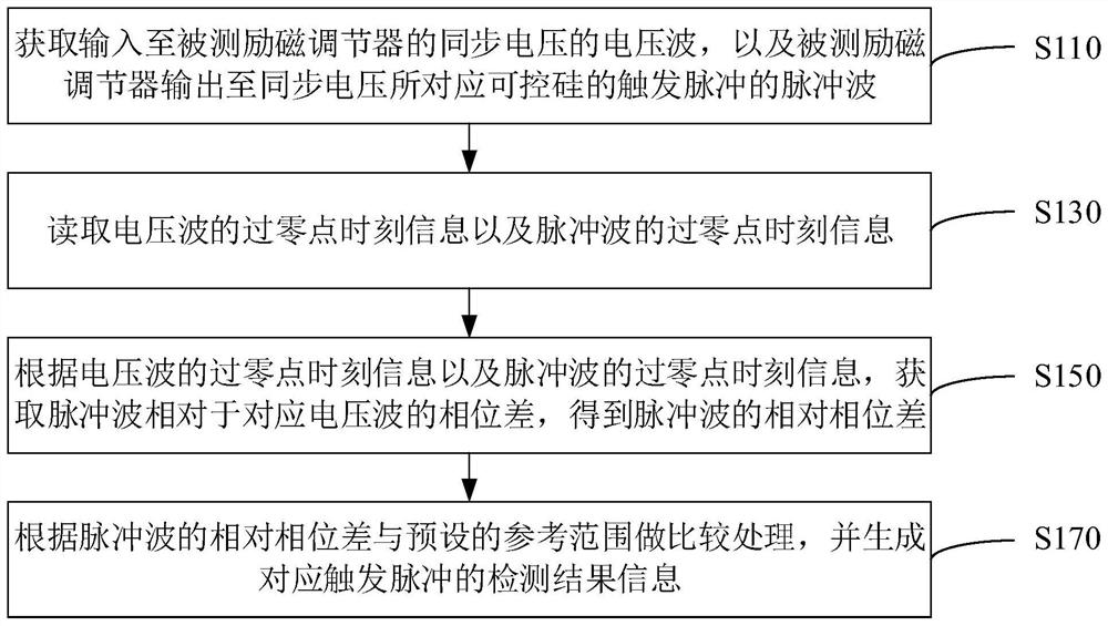
[0031] In one embodiment, as figure 1 As shown, a method for detecting a trigger pulse of an excitation regulator is provided, and the method is applied to a terminal as an example to illustrate, including the following steps:

[0032] S110: Acquire the voltage wave of the synchronous voltage input to the excitation regulator under test, and the pulse wave of the trigger pulse output by the excitation regulator under test to the thyristor corresponding to the synchronous voltage.

[0033] As a device that controls the output of the excitation power unit, the excitatio...


PUM


Abstract

The present application relates to a trigger pulse detection method, device, detector and test tooling of an excitation regulator. The excitation regulator trigger pulse detection method includes: obtaining the voltage wave of the synchronization voltage input to the excitation regulator under test, and the pulse wave of the trigger pulse output from the excitation regulator under test to the SCR corresponding to the synchronization voltage; reading the voltage wave The zero-crossing time information of the pulse wave and the zero-crossing time information of the pulse wave; according to the zero-crossing time information of the voltage wave and the zero-crossing time information of the pulse wave, the phase difference of the pulse wave relative to the corresponding voltage wave is obtained, and the relative phase difference of the pulse wave is obtained ; Wherein, the thyristor corresponding to the pulse wave corresponds to the synchronous voltage corresponding to the corresponding voltage wave; compare the relative phase difference of the pulse wave with the preset reference range, and generate the detection result information corresponding to the trigger pulse. Adoption of the application can prevent the user from using the tested excitation regulator with abnormal function to reduce the running stability of the generator.

Description

technical field [0001] The present application relates to the technical field of power electronics, and in particular, to a method, device, detector and test tool for detecting a trigger pulse of an excitation regulator. Background technique [0002] The excitation system is an important part of the generator, which has a great impact on the safe and stable operation of the power system and the generator itself. The excitation system generally includes an excitation power unit and an excitation regulator. The excitation power unit is used to provide excitation current to the rotor of the synchronous generator, while the excitation regulator controls the triggering of the thyristor according to the input synchronous voltage and a given regulation reference signal. The phase of the pulse is used to control the output of the excitation power unit. [0003] However, in the actual working process of the excitation system, the excitation regulator may function abnormally due to t...

Claims


Application Information

Patent Timeline
Patent Type & Authority Patents(China)
IPC IPC(8): G01R31/34
Inventor 申滔丁志龙廖晓斌胡清波
Owner HNAC TECH
Why Eureka
Try Eureka