Multi-frequency-point frequency hopping communication method based on power line carriers
A power line carrier and frequency hopping communication technology, which is applied in distribution line transmission systems, electrical components, transmission systems, etc., can solve problems such as poor real-time communication effects, inability to use frequency points for real-time communication, and data transmission failures, etc., to improve communication Real-time, not easy to monitor and crack, improve the effect of anti-interference
- Summary
- Abstract
- Description
- Claims
- Application Information
AI Technical Summary
Problems solved by technology
Method used
Image
Examples
Embodiment 1
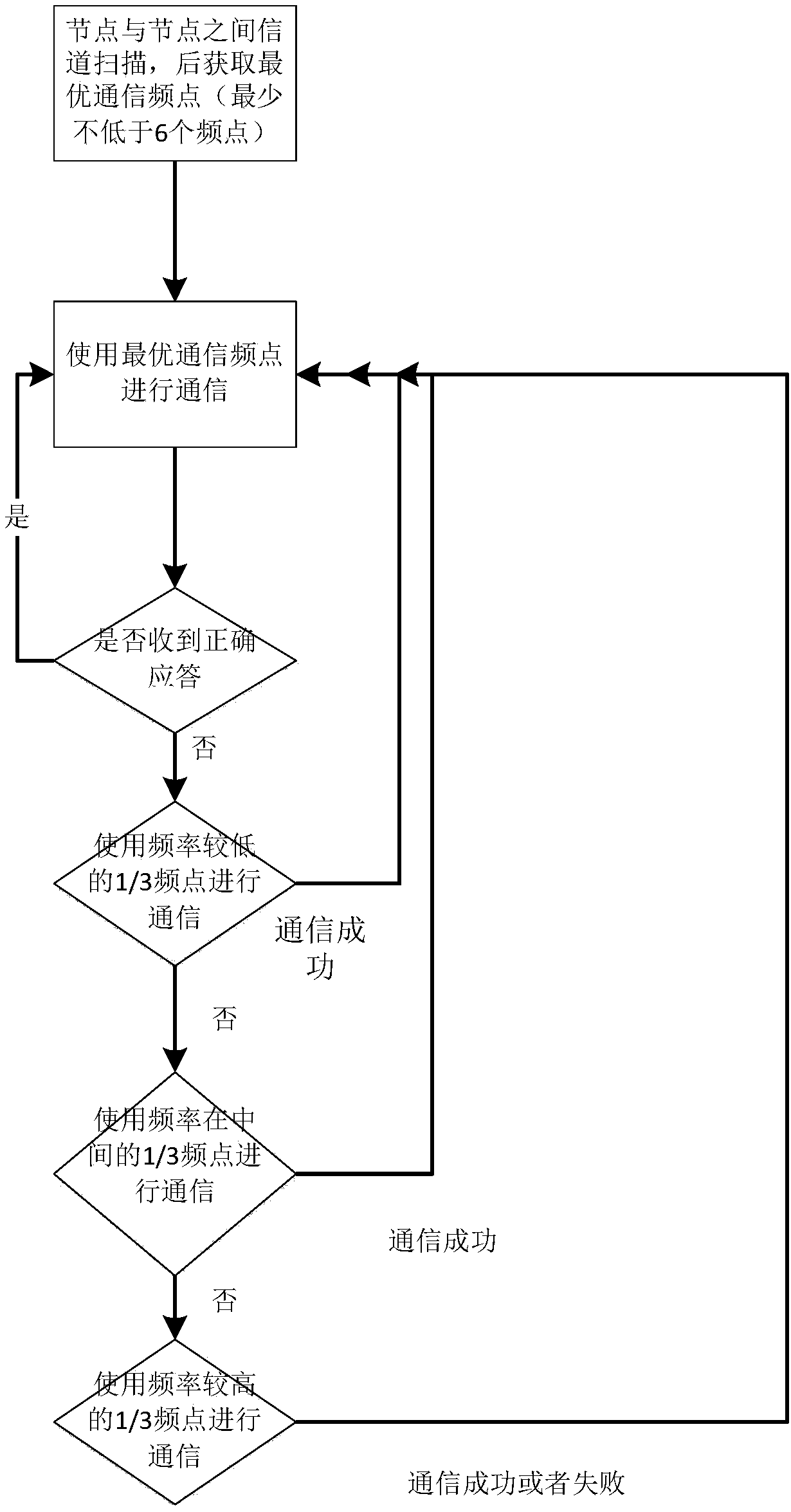
[0041] The present invention is mainly aimed at the automatic frequency hopping communication method in the communication process of the multi-frequency point carrier communication scheme, comprising the following steps:
[0042] A. Scan all frequency points between two nodes to obtain the optimal communication frequency between the two nodes, and set the life cycle of the communication channel; the life cycle of the communication channel is set according to the size of the network. In the network, the life cycle of the communication channel can be set to 15 minutes; in a network of 100 nodes, the life cycle of the communication channel can be set to 7 minutes;
[0043] B. Determine whether the life cycle is over, if not, use the optimal communication frequency point for communication between the two nodes; otherwise, go to step A;
[0044] C. During the life cycle, if the two nodes fail to communicate at the optimal communication frequency point, go to step D; otherwise, go t...
Embodiment 2
[0055] This example is the implementation of CELENEC A band:
[0056] 1) Select 36 frequency points in this frequency band (CELENEC A frequency band). Nodes and nodes use full-frequency point channel scanning during the first communication, and record the addresses of each other's nodes and several communication frequency points with the highest signal strength values. As the optimal frequency point, specifically:
[0057] After the node receives the request beacon or response beacon, it obtains the signal-to-noise ratio SNR value of all communication frequency points. The SNR value is divided into 3 segments: excellent, good, and poor. For example, the SNR value ranges from 80db to 0db, and the excellent value is 50db ~80db, good is 20~49db, and difference is 0~19db; if the number of frequency points with SNR values ranging from 50db to 80db is greater than or equal to 6, select all frequency points with SNR values ranging from 50db to 80db as the optimal communication F...
Embodiment 3
[0063] This embodiment is an FCC band implementation scheme, which is basically the same as Embodiment 2, except that 72 frequency points are selected in this frequency band, and 1 / 3 of all frequency points are 24 frequency points.
PUM
 Abstract
Description
Claims
Application Information
 - R&D
- Intellectual Property
- Life Sciences
- Materials
- Tech Scout
- Unparalleled Data Quality
- Higher Quality Content
- 60% Fewer Hallucinations
Browse by: Latest US Patents, China's latest patents, Technical Efficacy Thesaurus, Application Domain, Technology Topic, Popular Technical Reports.
© 2025 PatSnap. All rights reserved.Legal|Privacy policy|Modern Slavery Act Transparency Statement|Sitemap|About US| Contact US: help@patsnap.com

