A centrifugal separation device

A centrifugal separation and equipment technology, applied in centrifuges, centrifuges with rotating drums, etc., can solve the problems of poor sediment separation effect, easy turbidity of separation liquid, small separation factor, etc., and achieve improved solid-liquid separation effect, Improve the effect of low efficiency and short separation time

Active Publication Date: 2021-05-07
武汉太福制药有限公司
View PDF9 Cites 0 Cited by
  • Summary
  • Abstract
  • Description
  • Claims
  • Application Information

AI Technical Summary

Problems solved by technology

The horizontal centrifuge has the advantages of continuous operation without stopping, strong manufacturability, and good operating environment, but it also has the disadvantages of small separation factor, easy turbidity of the separation liquid and poor sediment separation effect

Method used


Image

  • A centrifugal separation device
  • A centrifugal separation device
  • A centrifugal separation device

Examples


Embodiment Construction

[0029] The following will clearly and completely describe the technical solutions in the embodiments of the present invention in conjunction with the embodiments of the present invention. Obviously, the described embodiments are only part of the embodiments of the present invention, not all of them. Based on the implementation manners in the present invention, all other implementation manners obtained by persons of ordinary skill in the art without making creative efforts belong to the scope of protection of the present invention.

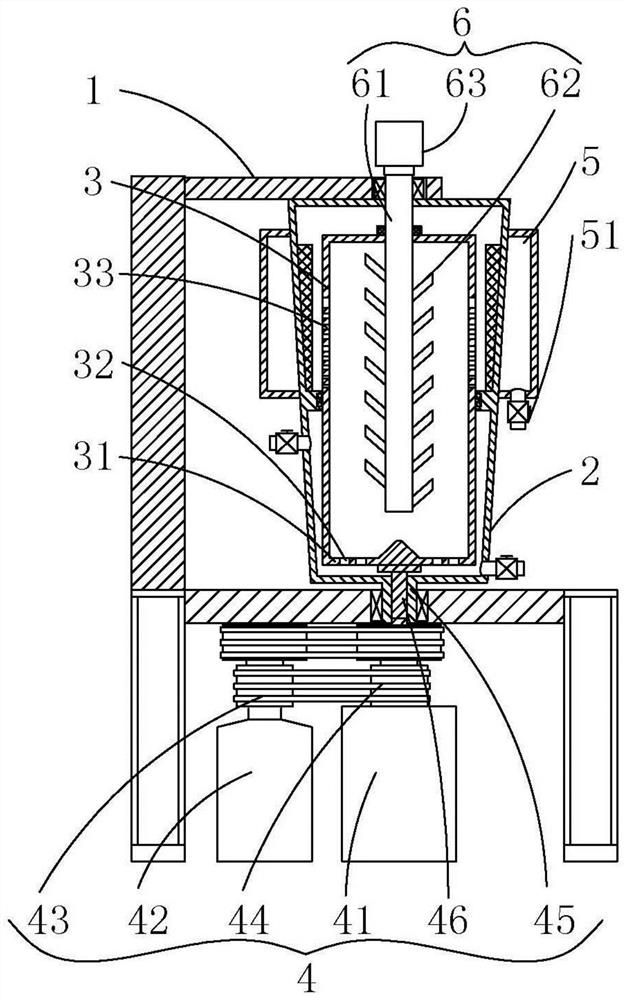
[0030] Such as figure 1 As shown, the present invention provides a centrifugal separation device, which includes a frame 1 , a casing 2 , a separation cylinder 3 , a differential drive device 4 , a confluence cylinder 5 and a stirring device 6 .

[0031] Frame 1 is the basis of the present invention and is used to support and fix other components.

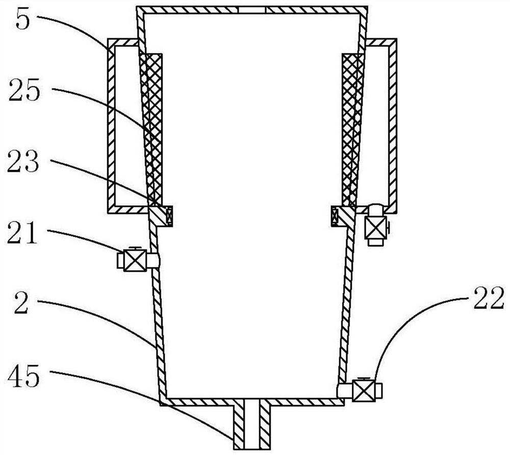
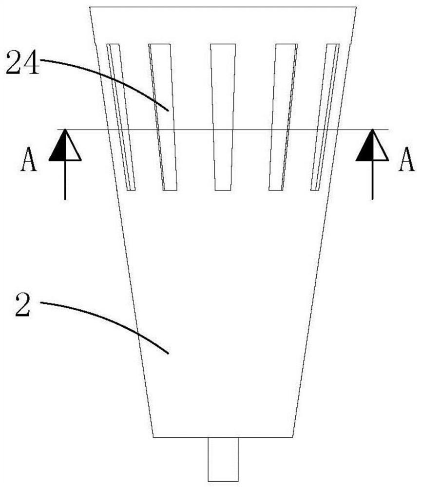
[0032] Depend on figure 1 combine figure 2 , image 3 and Figure 4 It can be seen that the to...


PUM


Abstract

The invention provides a centrifugal separation device, which includes a frame, a casing, a separation cylinder, a differential drive device, a confluence cylinder and a stirring device. There is an organic casing on the top of the frame, and a separation cylinder is arranged inside the casing. Both the casing and the separation cylinder are rotatably connected with the differential drive device; Liquid outlet pipe; a stirring device is arranged on the top of the frame, and the stirring device extends vertically downward along the vertical direction, successively penetrates the top of the casing and the separation cylinder, and extends into the inside of the separation cylinder. The feeding plate at the bottom of the separation cylinder of the present invention can realize the first separation, and the feeding plate cooperates with the stirring device to perform the second separation, and the materials taken out by the centrifugal force can be separated at the filter screen for the third time, gradually The effect of stage separation is more ideal; the size of the separation hole on the separation cylinder becomes larger step by step, which is conducive to the discharge of the supernatant and prevents the solid matter from flowing out of the separation cylinder.

Description

technical field [0001] The invention relates to the field of mechanical automation equipment, in particular to a centrifugal separation equipment. Background technique [0002] The common horizontal centrifuge rotates at a high speed through the rotating body to generate a great acceleration, so that the materials fed through the feed port are subjected to the centrifugal force. Since the centrifugal force received by the materials with different masses is different, the centrifugal force received is also different. Different, the impurities with small mass will be pushed to the inner layer, and the impurities with large mass will be thrown to the outer layer. The horizontal centrifuge has the advantages of continuous operation without stopping, strong manufacturability, and good operating environment, but it also has the disadvantages of small separation factor, easy turbidity of the separation liquid and poor sediment separation effect. Contents of the invention [0003...

Claims


Application Information

Patent Timeline
Patent Type & Authority Patents(China)
IPC IPC(8): B04B1/00B04B7/02B04B7/08B04B7/00B04B7/18B04B9/02B04B11/04B04B15/00
Inventor 周治国曲来志
Owner 武汉太福制药有限公司
Why Eureka
Try Eureka