Amorphous alloy production device

A production device and amorphous alloy technology, applied in the field of amorphous alloy production devices, can solve problems such as complex structure and uneven cooling, and achieve the effect of uniform cooling and simple structure

Active Publication Date: 2019-05-17
DONGGUAN EONTEC CO LTD
10 Cites 0 Cited by

AI-Extracted Technical Summary

Problems solved by technology

However, the current devices using the liquid quenching meth...

Method used

A kind of amorphous alloy production device provided by the present embodiment, by submerging spray head 20 in the supercooled liquid, and utilizing the airflow injection port 202 to eject the high-pressure air flow, blowing away the supercooled liquid in the current need injection range , so that the solution injection port 201 sprays the solution onto the mold 11, when the injection head 20 is removed, the supercooled liquid quickly covers the solution sprayed onto the mold 11 before rapid cooling, thereby forming an amorphous alloy blank; The advantages of simple structure and uniform cooling.
Further, the position of airflow ejection port 202 is higher than the position of solution ejection port 201, thereby can prevent the solution that the high-pressure airflow that...

Abstract

The invention discloses an amorphous alloy production device, which includes a main box body and a spraying head. A containing cavity is formed in the main box body and stored undercooling fluid, anda mould is placed in the containing cavity; the bottom end of the spraying head extends into the containing cavity and is submerged by the undercooling fluid, and the spraying head includes a solutionspraying opening and an airflow spraying opening; the airflow spraying opening is formed around the solution spraying opening; the airflow spraying opening blows the undercooling fluid, and then a solution is sprayed on the mould by the solution spraying opening; the spraying head is submerged in the undercooling fluid, the airflow spraying opening is used for spraying high pressure airflow to blow the undercooling fluid within the current required spraying range, so that the solution is sprayed on the mould by the solution spraying opening; and when the spraying head is moved away, the undercooling liquid quickly covers the solution before spraying to the mould, quickly cooling is conducted, and thus an amorphous alloy workblank is formed. The amorphous alloy production device has the advantages of being simple in structure and uniform in cooling.

Technology Topic

AirflowHigh pressure +1

Image

  • Amorphous alloy production device
  • Amorphous alloy production device
  • Amorphous alloy production device

Examples

  • Experimental program(1)

Example Embodiment

[0023] In order to make the objectives, features, and advantages of the present invention more obvious and understandable, the technical solutions in the embodiments of the present invention will be described clearly and completely in conjunction with the accompanying drawings in the embodiments of the present invention. Obviously, the following The described embodiments are only a part of the embodiments of the present invention, rather than all the embodiments. Based on the embodiments of the present invention, all other embodiments obtained by those of ordinary skill in the art without creative work shall fall within the protection scope of the present invention.
[0024] In the description of the present invention, it should be understood that the directions or positional relationships indicated by the terms "upper", "lower", "top", "bottom", "inner", and "outer" are based on the drawings shown The orientation or positional relationship is only for the convenience of describing the present invention and simplifying the description, rather than indicating or implying that the pointed device or element must have a specific orientation, be constructed and operated in a specific orientation, and therefore cannot be understood as a limitation of the present invention.
[0025] It should be noted that when a component is considered to be "connected" to another component, it can be directly connected to another component or a centrally arranged component may exist at the same time. When a component is considered to be "set on" another component, it can be directly set on another component or a centrally set component may exist at the same time.
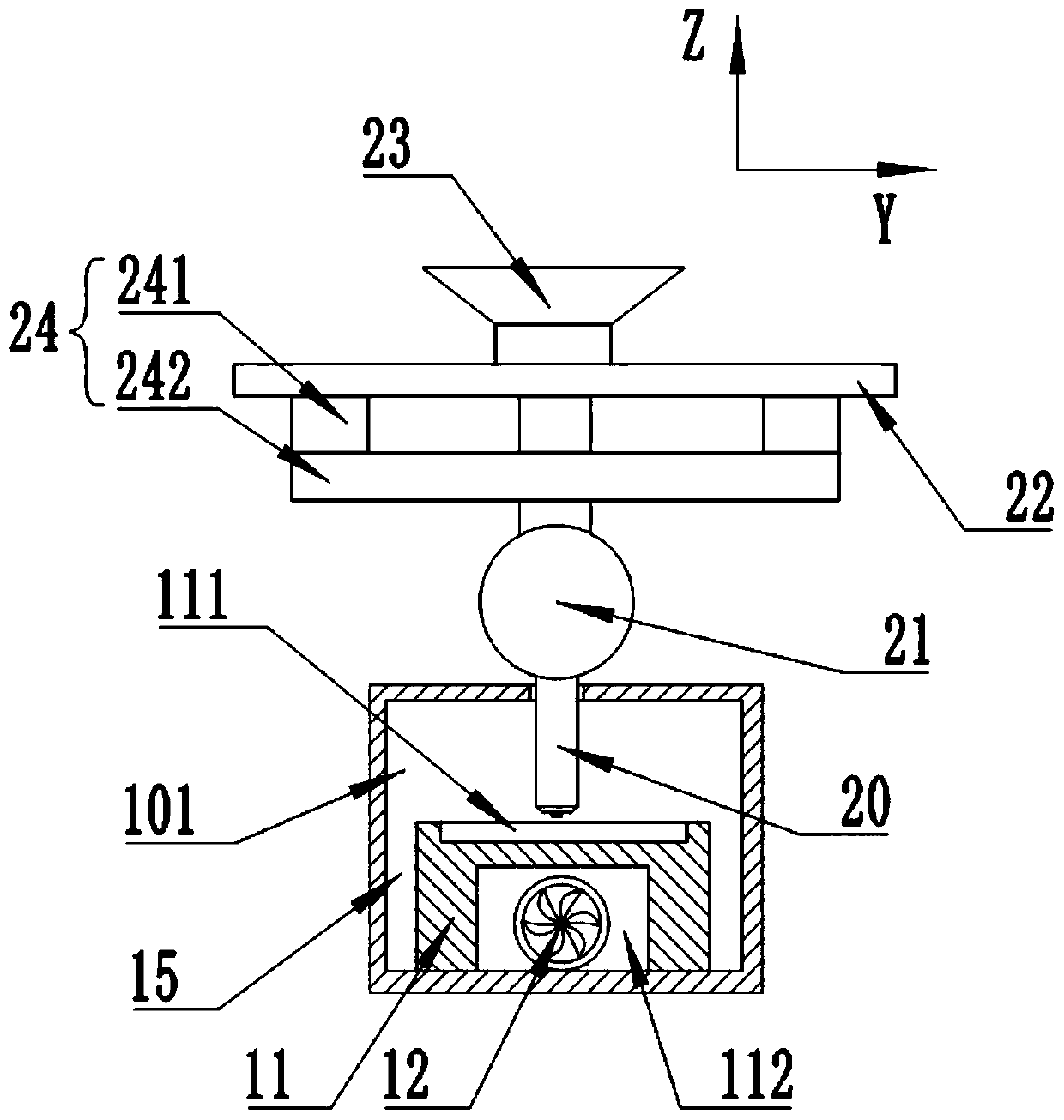
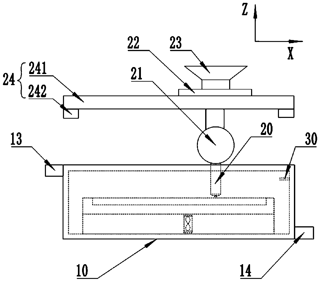
[0026] The technical solutions of the present invention will be further described below in conjunction with the drawings and specific implementations.
[0027] Please refer to Figure 1 to Figure 3 , An amorphous alloy production device, including a main box body 10 and a spray head 20, the main box body 10 is provided with a containing cavity 101, the containing cavity 101 stores supercooled liquid, and the containing cavity 101 is placed Mold 11; the bottom end of the spray head 20 extends into the containing cavity 101 and is submerged by the supercooled liquid; wherein, the bottom end of the spray head 20 is the end of the spray head 20 that sprays the solution; in this embodiment, the spray head 20 Located above the mold 11.
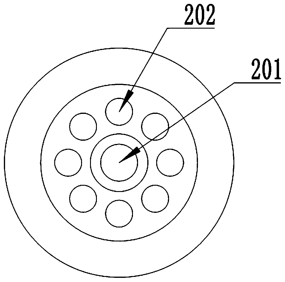
[0028] The top of the spray head 20 is connected with a resistance heater 21 for molten metal material. The resistance heater 21 is fixedly connected with a feeding funnel 23 through a pipe. The bottom of the feeding funnel 23 is fixedly connected with a driving fixing plate 22, which is connected to the driving fixing plate 22 There is a moving component 24 which drives and drives the fixed plate 22 to move in the XY plane to drive the jet to move in the XY plane, so that the jet head 20 can jet the solution according to requirements to form an amorphous alloy blank of a predetermined shape and size.
[0029] Specifically, the spray head 20 includes a solution spray port 201 and a gas flow spray port 202; the gas spray port 202 is arranged around the solution spray port 201; during spraying, a high-pressure gas flow is sprayed through the gas spray port 202 to blow off the supercooling within a certain range. So that the solution ejected from the solution ejection port 201 can effectively fall onto the mold 11.
[0030] The working principle is: the metal raw materials for making amorphous alloys are put in through the feeding funnel 23 and flow into the resistance heater 21 for heating. The heated molten solution is sprayed through the solution spray port 201, and the gas flow spray port 202 sprays high pressure. The air flow blows away the supercooled liquid within the current need to spray, so that the solution injection port 201 sprays the solution onto the mold 11. When the spray head 20 is removed, the supercooled liquid quickly covers the previously sprayed solution on the mold 11. Perform rapid cooling to form an amorphous alloy blank.
[0031] Further, the position of the airflow injection port 202 is higher than the position of the solution injection port 201, thereby preventing the high-pressure airflow sprayed from the airflow injection port 202 from affecting the solution sprayed from the solution injection port 201, and at the same time avoiding pre-cooling.
[0032] Specifically, the top surface of the mold 11 is provided with a groove 111 so that the solution can be sprayed into the groove 111 to form a predetermined shape; the bottom surface of the mold 11 is provided with a circulation channel 112 extending in the X-axis direction, and the circulation channel 112 is installed There is a circulating pump 12 through which the supercooled liquid in the accommodating cavity 101 is circulated to avoid the problem of poor quality of the amorphous alloy due to the local high temperature of the supercooled liquid.
[0033] Specifically, the main tank 10 is provided with a supercooled liquid inlet 13 and a supercooled liquid outlet 14. The supercooled liquid inlet 13 and the supercooled liquid outlet 14 are both connected to the containing cavity 101, and the containing cavity 101 is provided There is a temperature sensor 30; the temperature sensor 30 detects the temperature of the subcooled liquid in the accommodating cavity 101 in real time, and performs corresponding water intake and drainage according to temperature changes, so as to realize the constant temperature control of the subcooled liquid in the accommodating cavity 101.
[0034] Specifically, the motion component 24 includes an X-axis linear module 241 and a Y-axis linear module 242. The Y-axis linear module 242 drives the X-axis linear module 241 to move on the Y-axis, and the X-axis linear module 241 drives the jet head 20. It moves on the X axis; the X-axis linear module 241 and the Y-axis linear module 242 realize the movement of the spray head 20 in the XY plane.
[0035] In the amorphous alloy production device provided by this embodiment, the spray head 20 is submerged in the supercooled liquid, and the high-pressure air flow is sprayed from the air jet port 202 to blow off the supercooled liquid in the current required spray range, thereby making The solution spray port 201 sprays the solution onto the mold 11. When the spray head 20 is removed, the supercooled liquid quickly covers the solution sprayed on the mold 11 and cools quickly to form an amorphous alloy blank; it has a simple structure, The advantages of uniform cooling.
[0036] As mentioned above, the above embodiments are only used to illustrate the technical solutions of the present invention, but not to limit them; although the present invention has been described in detail with reference to the foregoing embodiments, those of ordinary skill in the art should understand that: The technical solutions recorded in the embodiments are modified, or some of the technical features are equivalently replaced; these modifications or replacements do not cause the essence of the corresponding technical solutions to deviate from the spirit and scope of the technical solutions of the embodiments of the present invention.

PUM

no PUM

Description & Claims & Application Information

We can also present the details of the Description, Claims and Application information to help users get a comprehensive understanding of the technical details of the patent, such as background art, summary of invention, brief description of drawings, description of embodiments, and other original content. On the other hand, users can also determine the specific scope of protection of the technology through the list of claims; as well as understand the changes in the life cycle of the technology with the presentation of the patent timeline. Login to view more.

Similar technology patents

Body condition measuring device

InactiveUS20050234351A1simple structure
Owner:DENSO CORP

Magnetic cooling apparatus and control method thereof

ActiveUS20130180263A1simple structure
Owner:SAMSUNG ELECTRONICS CO LTD

Dual-Drivetrain of Power-Assist Vehicle

InactiveUS20100181130A1enhance uphill momentumsimple structure
Owner:CHOU WEN CHENG

Classification and recommendation of technical efficacy words

  • Simple structure
  • Cool evenly

Sharing system for air-conditioning coat

InactiveCN107440179ASimple structureeasy to wear
Owner:QINGDAO HAIER AIR CONDITIONER GENERAL CORP LTD

Feeding device of sorter of batteries plate

InactiveCN101357717ASimple structurecooperate well
Owner:NANJING NORMAL UNIVERSITY

Emergency parachuting device and method for multiple-rotor unmanned aerial vehicle

InactiveCN103895870Aavoid aircraft crashSimple structure
Owner:SOUTH CHINA AGRI UNIV +1

Combined type preform taking and cooling device and method thereof

ActiveCN101767423ACool evenlyImprove cooling efficiency
Owner:SHENZHEN INST OF ADVANCED TECH

Quenching and cooling device

ActiveCN106916927ACool evenlyhigh degree of automation
Owner:QINGDAO TAIDE AUTOMOBILE BEARING

Fiber wind cooler

InactiveCN103469320ASimple structureCool evenly
Owner:WUXI ZHONGWANG 4D TECH
Why Eureka
Try Eureka