Milling Chatter Control Method Based on Asymmetric Stiffness Regulation of Spindle System

A control method, milling chatter technology, applied in manufacturing tools, metal processing equipment, measuring/indicating equipment, etc., can solve the problems of weakening damping effect, shortening tool life, scrapping of workpieces, etc., to achieve energy saving, large milling stability area , The effect of the control method is simple and easy to implement

Active Publication Date: 2020-06-19
无锡鸣山机电科技有限公司
View PDF2 Cites 0 Cited by
  • Summary
  • Abstract
  • Description
  • Claims
  • Application Information

AI Technical Summary

Problems solved by technology

During the milling process, due to the change of the spindle characteristics and the weakening of the damping effect, chatter instability is prone to occur, resulting in the scrapping of the workpiece and shortening the tool life, which seriously limits the improvement of machining accuracy and efficiency.

Method used


Image

  • Milling Chatter Control Method Based on Asymmetric Stiffness Regulation of Spindle System
  • Milling Chatter Control Method Based on Asymmetric Stiffness Regulation of Spindle System
  • Milling Chatter Control Method Based on Asymmetric Stiffness Regulation of Spindle System

Examples


Embodiment

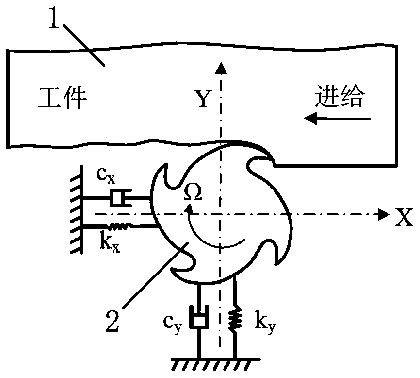
[0073] Implementation examples of the present invention adopt such as Figure 4 The milling spindle system shown is analyzed.

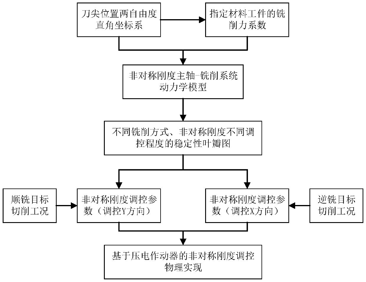
[0074] Using a 10mm-diameter 3-blade milling cutter, take the milling cutter tip as the origin of the coordinate axis, take the milling feed direction as the X-axis direction, and take the direction perpendicular to the feed direction and the tool axis as the Y-axis direction to establish two degrees of freedom Cartesian coordinate system.

[0075] Arrange an acceleration sensor along the X-axis direction at the tip of the milling cutter, use a force hammer to excite the tip of the milling cutter on the opposite side of the sensor, measure the frequency response function curve, and identify the modal mass m of the main mode x , stiffness k x and damping c x . Perform the same operation in the Y-axis direction to identify the modal mass m y , stiffness k y and damping c y . The results of modal parameter identification are shown in Table 1.

...


PUM


Abstract

The invention discloses a milling and cutting flutter control method based on asymmetric stiffness regulation of a main shaft system. The milling and cutting flutter control method based on the asymmetric stiffness regulation of the main shaft system comprises the steps that (1) a rectangular coordinate system based on a cutting direction is established; (2) an experimental method is used for identifying a cutting force coefficient of a specified material workpiece; (3) an asymmetric stiffness main shaft-milling and cutting system dynamics model is established; (4) a system characteristic equation is obtained, and a smoothly and inversely milling stability leaf-valve graph with different adjustment degrees of the non-symmetric stiffness is calculated; (5) a suitable asymmetric stiffness combination is selected according to the smoothly and inversely milling and the target cutting parameters; and (6) a piezoelectric actuator is used for realizing the physical regulation of the asymmetric stiffness. According to the milling and cutting flutter control method based on the asymmetric stiffness regulation of the main shaft system, the stiffness of the main shaft X and the Y direction before cutting or on-line can be asymmetrically controlled according to the two different cutting modes of smoothly and inversely milling, the cutting stability of the system can be effectively improved, the flutter is restrained, and the processing precision and the efficiency are improved. Meanwhile, the method is easy to implement and is beneficial to industrial practical application.

Description

technical field [0001] The invention belongs to the technical field of milling processing control, and in particular relates to a milling chatter control method based on asymmetric rigidity control of a spindle system. Background technique [0002] Milling is a cutting process that is widely used, especially in the field of aerospace, where high speed, high efficiency, and milling have become the mainstream of mechanical processing. During the milling process, due to changes in the characteristics of the spindle and weakening of the damping effect, chatter instability is prone to occur, resulting in scrapped workpieces and shortened tool life, which severely limits the improvement of machining accuracy and efficiency. Therefore, controlling milling chatter is of great significance to the realization of high-speed and high-efficiency milling and the improvement of workpiece processing quality. [0003] For the control of milling chatter, a lot of researches have been done at...

Claims


Application Information

Patent Timeline
Patent Type & Authority Patents(China)
IPC IPC(8): B23Q17/12
Inventor 曹宏瑞李登辉陈雪峰张兴武
Owner 无锡鸣山机电科技有限公司
Why Eureka
Try Eureka