Supercharge Your Innovation With Domain-Expert AI Agents!

Positive drive lift

A technology of forced drive and elevator, which is applied to elevators, elevators, transportation and packaging in buildings, etc. It can solve problems such as elevator structure mismatch, achieve compact and reasonable overall structure, simplify component structure, and reduce roof construction. Effect

Pending Publication Date: 2019-05-17
多普勒电梯股份有限公司
View PDF10 Cites 0 Cited by
  • Summary
  • Abstract
  • Description
  • Claims
  • Application Information

AI Technical Summary

Problems solved by technology

[0007] The purpose of the present invention is to provide a forced-drive elevator for the problem that the elevator structure in the prior art does not match the elevator shaft of the existing villa. It meets the requirements of elevator installation on the height of the top floor of the hoistway, saves the installation space on the roof, and the elevator structure is more stable in force; at the same time, the structure of the car floor is more compact, reducing the requirements for the depth of the shaft pit

Method used


Image

  • Positive drive lift
  • Positive drive lift
  • Positive drive lift

Examples


Embodiment 1

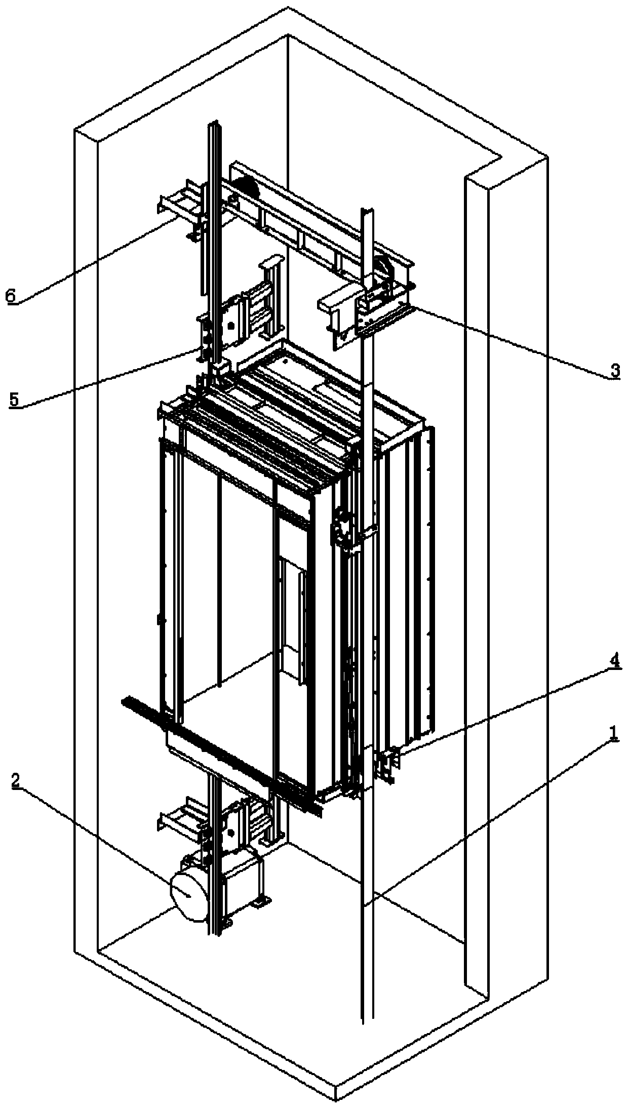
[0038]A forced-drive elevator includes a car guide rail 1, a main engine 2, an anti-sheave device 3, a car floor assembly 4, and a traction rope.

[0039] Wherein, the car guide rail 1 includes two guide rails with a T-shaped cross section, and the two guide rails are arranged symmetrically on both sides of the hoistway;

[0040] The host 2 is fixed at the bottom of the hoistway, and the host 1 is arranged between the car guide rail 1 on one side and the wall of the hoistway.

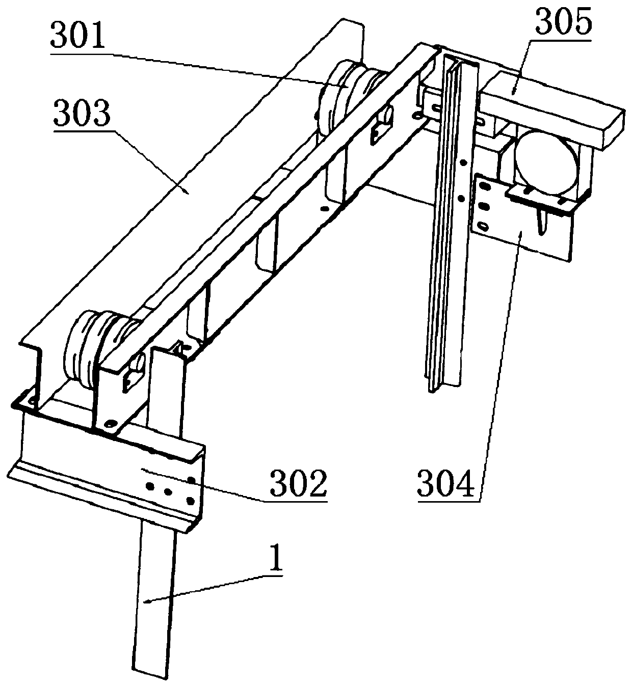
[0041] Unlike the prior art where the anti-sheave device is fixed on the top of the hoistway, the anti-sheave device 3 is fixedly arranged on the upper part of the car guide rail 1 in this embodiment. The anti-sheave device 3 comprises an anti-sheave support beam assembly, and the anti-sheave support beam assembly is fixed on the car guide rail 1 top. The anti-sheave support beam assembly includes two short beams 302 and two long beams 303, the two short beams 302 are horizontally and symmetrically arr...

Embodiment 2

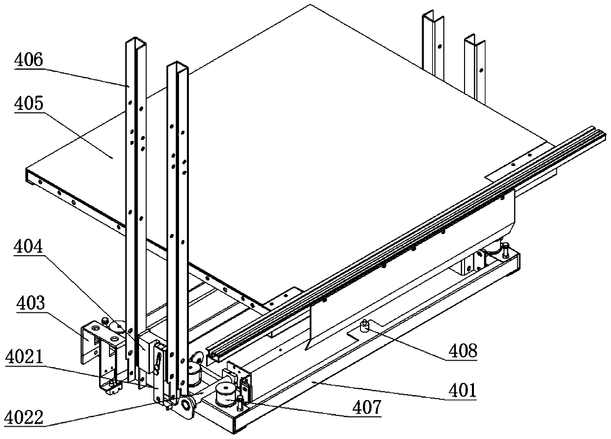
[0049] On the basis of Embodiment 1, two columns 406 are arranged on the left side wall and the right side wall of the car bottom bracket 401, and the car guide shoe 404 is fixed between the two columns 406; the safety gear device includes a safety gear 4021 , safety gear linkage device 4022 ; the safety gear 4021 is set on the car guide shoe 404 , and the safety gear linkage device 4022 is set between the car floor bracket 401 and the car floor 405 . The car rope end plate 403 is arranged as a few characters and the opening is downward; the two arms of the car rope end plate 403 are fixed on the two side walls of the car bracket 401 .

[0050] After adopting the above structure, the structure of the car floor in this embodiment is more compact, which reduces the space occupation in the direction of the car height, thereby reducing the requirement for the depth of the pit, and is suitable for use in the construction of villa elevators.

Embodiment 3

[0052] On the basis of Embodiment 2, the shock-absorbing layer includes four shock-absorbing rubber pads 407 evenly arranged on both sides of the top surface of the car bottom bracket 401, and a weighing device is also arranged on the top surface of the car bottom bracket 401. 408, the shock absorbing rubber pad 407, and the weighing device 408 are all connected with the bottom surface of the car floor 405.

[0053] In this embodiment, an accommodating space is provided between the car floor 405 and the car floor bracket 401, and the shock absorbing layer is arranged in the accommodating space. The shock-absorbing rubber pad 407 is used to reduce the vibration of the elevator during starting, stopping and running, so as to increase the comfort of passengers. The uniform and symmetrical arrangement of the shock-absorbing rubber pads can further improve the shock-absorbing effect, so as to maintain good shock-absorbing performance without affecting the structural strength of the...


PUM


Abstract

The invention discloses a positive drive lift, and belongs to the field of positive drive lifts. The positive drive lift comprises car guide rails, a host machine, a diversion sheave device, a car bottom assembly and a traction rope. The car guide rails are symmetrically arranged on the two sides of a shaft. The host machine is fixed to the bottom of the shaft. The diversion sheave device is fixedly arranged on the upper portions of the car guide rails. The car bottom assembly comprises a car bottom bracket, a shock absorption layer and a car bottom plate which are sequentially arranged from bottom to top. The left side wall and the right side wall of the car bottom bracket are each provided with a safety gear device, a car rope hitch plate and a car guide shoe. The bottom end heights of the safety gear devices, the car rope hitch plates and the car guide shoes are all larger than the height of the bottom end of the car bottom bracket. The car bottom bracket can slide on the car guiderails in the axial direction of the car guide rails in a reciprocating manner through the car guide shoes. One end of the traction rope is connected to the host machine, and the other end of the traction rope is connected with the car rope hitch plates after penetrating through the diversion sheave device. By means of the positive drive lift, the requirement of lift installation for the top layerheight and the bottom pit depth of the shaft is reduced, and the lift installation construction amount is decreased.

Description

technical field [0001] The invention belongs to the field of forced drive elevators, and in particular relates to a forced drive elevator used in villas. Background technique [0002] In order to prevent the elevator from going up or down too fast and causing accidents, safety gears are generally installed on both sides of the elevator. When the elevator runs overspeed, it will trigger the action of the speed limiter. The safety gear clamps the elevator guide rail to stop the elevator car. now [0003] In the prior art, due to the limitation of the house structure, the height of the top floor of the villa elevator shaft and the depth of the pit are relatively small. However, in the existing villa elevators, the safety gear of the forced-drive elevator usually adopts the upper safety gear structure, which often needs to occupy a large space on the top floor of the well and the bottom pit, and at the same time, the structure is more complicated and the cost is higher. At th...

Claims


Application Information

Patent Timeline
Patent Type & Authority Applications(China)
IPC IPC(8): B66B11/02B66B5/00B66B1/06
Inventor 龚清华肖林吴永贵匡南辉张明赵文秋
Owner 多普勒电梯股份有限公司
Features
  • R&D
  • Intellectual Property
  • Life Sciences
  • Materials
  • Tech Scout
  • Unparalleled Data Quality
  • Higher Quality Content
  • 60% Fewer Hallucinations
Learn More