
Full-prefabricated concrete anti-collision guardrail and construction method

A technology of prefabricated concrete and anti-collision barriers, which is applied to bridge parts, erection/assembly of bridges, bridges, etc., can solve the problems of unrealized full prefabrication of concrete anti-collision barriers, speed up the bridge construction cycle, and difficult to guarantee the appearance quality, so as to reduce the Construction process, good applicability, effect of reducing dosage

Active Publication Date: 2019-05-17
WISDRI ENG & RES INC LTD +1
View PDF9 Cites 2 Cited by
  • Summary
  • Abstract
  • Description
  • Claims
  • Application Information

AI Technical Summary

Problems solved by technology

The traditional bridge concrete anti-collision guardrail construction technology often adopts the cast-in-place method, that is, the bridge deck is bound with steel bars, and the guardrail is poured after the formwork is erected. This process is not conducive to speeding up the bridge construction period, and has disadvantages such as environmental pollution and noise pollution. When the exterior of the anti-collision guardrail has landscape modeling requirements, the construction is more complicated, and the appearance quality is not easy to guarantee
[0003] At present, there are construction techniques for partially prefabricated concrete anti-collision barriers. The common practice is that the concrete anti-collision barriers are prefabricated in segments, and a part of the post-casting belt is reserved between the guardrails and the bridge deck, and the reserved steel joints are bound and welded on site. The construction period is still long, and this method has not yet achieved full prefabrication of concrete crash barriers

Method used


Image

  • Full-prefabricated concrete anti-collision guardrail and construction method
  • Full-prefabricated concrete anti-collision guardrail and construction method
  • Full-prefabricated concrete anti-collision guardrail and construction method

Examples


Embodiment Construction

[0031] The present invention will be described in detail below in conjunction with the accompanying drawings and embodiments.

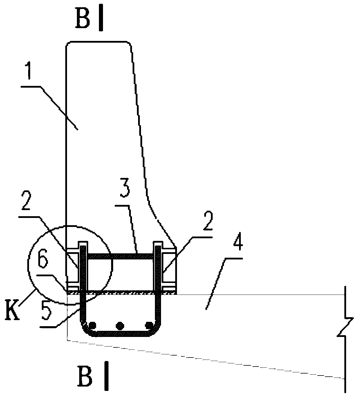
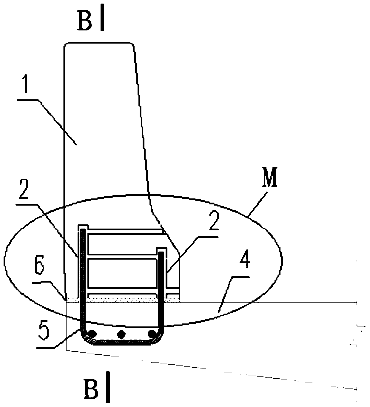
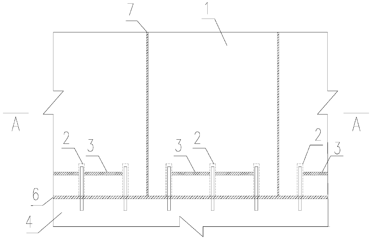
[0032] refer to Figure 1 to Figure 6 As shown, the full prefabricated concrete crash barrier in an embodiment provided by the present invention includes several jointed precast concrete crash barrier segments 1, and each precast concrete crash barrier segment 1 bottom is provided with a connecting device 2. The connecting device 2 is connected to the top plate 4 of the bridge deck;

[0033] The connection device 2 includes a steel casing 21, a slurry inlet pipe 22 and a slurry outlet pipe 23. The steel casing 21 is sleeved on the steel bar 5 reserved for the bridge deck, and the slurry inlet pipe 22 and the slurry outlet pipe 23 are respectively connected to the steel casing 21. .

[0034] Further, the steel sleeves 21 are connected by casing connecting steel bars 3 to enhance the connection force between the sleeve and the concrete; the slurry inl...


PUM


Abstract

The invention discloses a full-prefabricated concrete anti-collision guardrail and a construction method. The guardrail comprises a plurality of spliced prefabricated concrete anti-collision guardrailsections, wherein a connecting device is arranged at the bottom of each prefabricated concrete anti-collision guardrail section; the connecting device is connected with the top plate of a bridge surface; the connecting devices comprise steel casings, pulp inlet tubes and pulp outlet tubes; bridge surface reserved reinforcing steel ribs are sleeved by the steel casings; the pulp inlet tubes and the pulp outlet tubes are respectively connected with the steel casings. The mounting efficiency can be improved, full prefabrication of a concrete anti-collision guardrail can be achieved, on-site construction procedures can be reduced, and the mounting time can be shortened.

Description

technical field [0001] The invention relates to the technical field of bridge engineering, in particular to a fully prefabricated concrete anti-collision barrier and a construction method. Background technique [0002] With the continuous acceleration of urbanization in our country, the construction progress of infrastructure such as roads and bridges is advancing rapidly. At the same time, with the progress of social civilization, the requirements for the progress of bridge construction, environmental protection, and aesthetics are also getting higher and higher. The traditional bridge concrete anti-collision guardrail construction technology often adopts the cast-in-place method, that is, the bridge deck is bound with steel bars, and the guardrail is poured after the formwork is erected. This process is not conducive to speeding up the bridge construction period, and has disadvantages such as environmental pollution and noise pollution. When the exterior of the anti-collis...

Claims


Application Information

Patent Timeline
IPC IPC(8): E01D19/10E01D21/00
Inventor 王江刘宇闻程建波
Owner WISDRI ENG & RES INC LTD
Learn More