Mechanical clutch device

A technology of mechanical clutches and rotating shafts, applied in the direction of mechanically driven clutches, clutches, mechanical equipment, etc., can solve the problems of high manufacturing cost, large space size, complex structure, etc., and achieve the effect of simplified structure, ingenious conception and novel design

Pending Publication Date: 2019-05-17
盐城永弘机械有限公司
View PDF6 Cites 1 Cited by
  • Summary
  • Abstract
  • Description
  • Claims
  • Application Information

AI Technical Summary

Problems solved by technology

[0004] In order for the clutch device to have a fixed position function, in the prior art, one is to use a spring to press the steel ball, and the steel ball is against the socket hole attached to the control handle. To change the position, the handle needs to be pulled hard to overcome the spring. pressure and steel ball friction to ensure that the original position is not easy to chan

Method used


Image

  • Mechanical clutch device
  • Mechanical clutch device
  • Mechanical clutch device

Examples


Embodiment Construction

[0026] The technical solutions in the embodiments of the present invention are clearly and completely described below in conjunction with the accompanying drawings in the embodiments of the present invention; obviously, the described embodiments are only some of the embodiments of the present invention, not all of them, and also include other methods the embodiment. Based on the embodiments of the present invention, other embodiments obtained by other inventors without making creative efforts in this technical field shall all fall within the protection scope of the present invention.

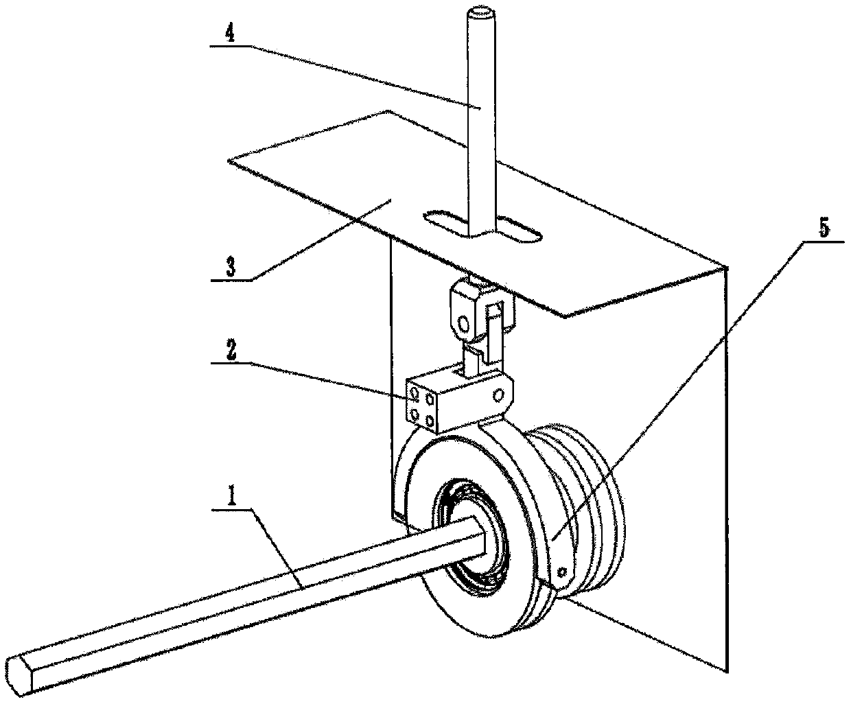
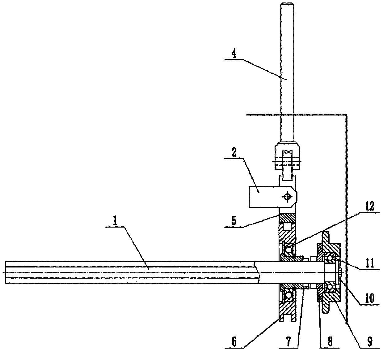
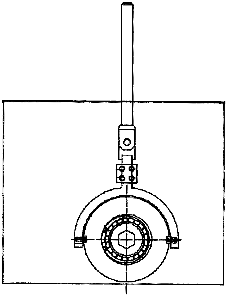
[0027] figure 1 It is an overall axonometric view of the clutch device in an embodiment of the present invention, figure 2 is the right side view of the device, image 3 is the front view of the device, Figure 4 is a top view of the device; if Figure 1-Figure 4 , the clutch device in the present embodiment consists of a rotating shaft 1, a bracket 2, a track plate 3, a control handle 4, a...


PUM


Abstract

The invention provides a mechanical clutch device. The mechanical clutch device comprises a rotating shaft, a support, a track plate, a control handle, a shifting fork, a circular ring, a tooth embedding sliding sleeve, a tooth embedding cover, a chain wheel, a bearing pressing plate, a bearing A and a bearing B; the clutch device is applied to a whole machine system, the support, the track plate,the rotating shaft and the chain wheel are mounted on other parts of the whole machine system, and the rotating shaft and the chain wheel are in transmission connection with the whole machine system;when the control handle is manually pulled to move along an axial groove of the track plate, the shifting fork, the circular ring and the tooth embedding sliding sleeve are driven to axially move onthe rotating shaft, the tooth embedding sliding sleeve and the tooth embedding cover are connected in an embedded manner or separated, and power transmission between the chain wheel and the rotating shaft is executed or cut off; when the control handle is pulled to be in a vertical groove at two ends, embedding teeth are completely engaged or separated, and the clutch device is kept in a separation state or a reunion state; and when the control handle rod is pulled to move along the vertical groove to the tail end, the state of the embedding teeth is unchanged, the position of the handle rod is fixed, and the clutch device is reliably separated and engaged, until the state is changed by the next manual operation.

Description

technical field [0001] The invention relates to the technical field of agricultural machinery transmission, in particular to the design and application of a toothed clutch device on an agricultural work tool. Background technique [0002] Agricultural work tools are common agricultural machinery. Common agricultural work machines include seeders, fertilizers, or compound work machines combined with other functions, including multiple sets of work parts that are the same or similar between rows of one function, and a variety of Different types of working parts with different functions; different agronomic requirements in different places have special requirements for agricultural machinery, and there are often choices between the functions of the working tools, between rows and rows, between agricultural machinery and power sources, that is, whether each part works The problem; the machine system usually uses a clutch device to determine the transmission or cut-off of the pow...

Claims


Application Information

Patent Timeline
IPC IPC(8): F16D11/14
Inventor 郝汉胜朱元兵周志奎
Owner 盐城永弘机械有限公司
Why Eureka
Try Eureka