
Gas exhaust valve type carbon dioxide cracking tube and parallel cracking device thereof

A technology of carbon dioxide and cracking tubes, which is applied in the direction of weapon accessories, blasting cylinders, blasting, etc., and can solve the problems of large-scale foreign operations that are difficult to meet blasting requirements, low blasting force, and low power.

Inactive Publication Date: 2019-05-17
戴矿明
View PDF1 Cites 1 Cited by
  • Summary
  • Abstract
  • Description
  • Claims
  • Application Information

AI Technical Summary

Problems solved by technology

[0002] In the existing blasting technology, most of the blasting tubes are used to replace the traditional explosives during the blasting operation. The existing carbon dioxide blasting device, such as the carbon dioxide blasting device in the invention patent with application number 201520141713.X, has a top end of the blasting tube. A filling head with a filling hole. The filling head is provided with a valve core matching the filling hole and a terminal post matching the detonating device. The terminal post covered with an insulating tube is connected to the terminal screw. The tail of the blasting tube There is a venting head with a blasting hole and a decompression hole at the end, a bursting disc is set between the venting head and the blasting tube, the first wire passing through the venting head, the blasting tube, and the filling head and the first wire connected to the shell of the blasting tube The two wires are respectively connected to the power supply and can be used repeatedly, but the directional blasting force is small, and it is difficult to meet the blasting requirements for large-scale external operations. If there is too much moisture, the cracking tube will not be fully inflated during the inflation process, resulting in a decrease in blasting power; moreover, the current carbon dioxide blasting tubes generally use a carbon dioxide cracking tube to independently blast the power is relatively small

Method used


Image

  • Gas exhaust valve type carbon dioxide cracking tube and parallel cracking device thereof
  • Gas exhaust valve type carbon dioxide cracking tube and parallel cracking device thereof
  • Gas exhaust valve type carbon dioxide cracking tube and parallel cracking device thereof

Examples


Embodiment 1

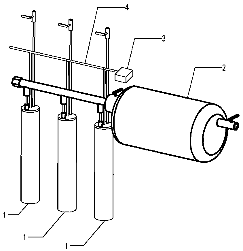
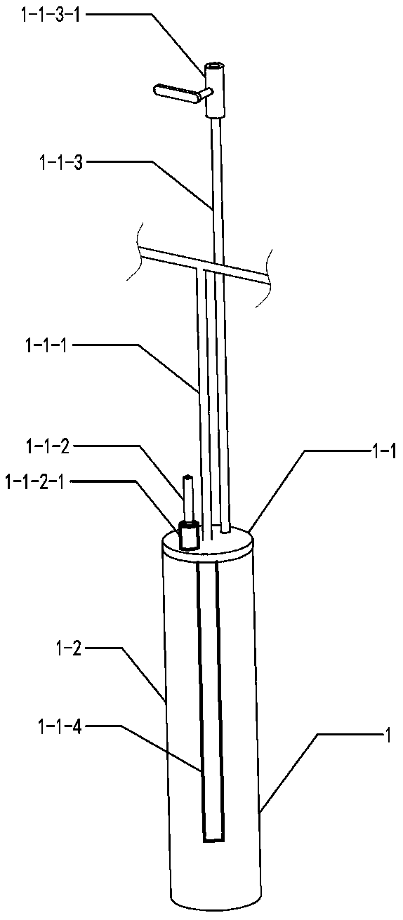
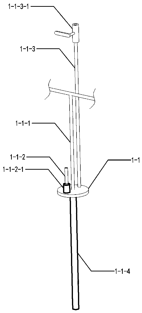
[0023] It can be seen from the content of the invention that an exhaust valve type carbon dioxide cracking tube and its parallel cracking device are composed of a venting type cracking tube 1, a gas parallel device 2, a detonator 3, and an electronic fuze line 4; The gas cracking tube 1 consists of a sealing plate 1-1, a tube body 1-2, an electronic fuze 1-1-1, an air intake pipe 1-1-2, an air intake check valve 1-1-2-1, an exhaust Pipe 1-1-3, exhaust pipe valve 1-1-3-1, composition, and on sealing plate 1-1, be provided with air inlet hole 1-1-5, fuze hole 1-1-6, exhaust hole 1-1-7; the electronic fuze 1-1-1 passes through the fuze hole 1-1-6 to connect with the detonator 1-1-4; the air intake check valve 1-1-2-1 Installed between the air intake hole 1-1-5 and the air intake pipe 1-1-2; the lower end of the exhaust pipe 1-1-3 is welded to the mouth of the exhaust hole 1-1-7, and the exhaust pipe valve 1-1-3-1 is installed on the upper end of the exhaust pipe 1-1-3; the gas p...

Embodiment 2

[0050] In order to realize the exhaust function of the cracking tube in the present invention, an exhaust pipe 1-1-3 is provided on the exhausting cracking tube 1 .

Embodiment 3

[0052] In order to realize rapid removal of impurities in the gas, the present invention designs the inlet pipe 1-1-2 and the exhaust pipe 1-1-3 at the same end of the exhaust-type cracking pipe 1 .


PUM


Abstract

The invention discloses a gas exhaust valve type carbon dioxide cracking tube and a parallel cracking device thereof. The gas exhaust valve type carbon dioxide cracking tube comprises gas exhaust typecracking tubes, a gas parallel device, an exploder and an electronic fuse wire. The parallel cracking device can be used for detonating while connecting multiple gas exhaust type cracking tubes in parallel, and improves blasting power of single gas exhaust type cracking tube better; while an electronic fuse is accessed to a power supply, a heating tube quickly acts for enabling carbon dioxide inthe outer tube to instantly gasify and expand, so that pressure in the tube is quickly increased, the outer tube is expanded to be broken, the whole detonation process is very quick, and production efficiency is high; and the gas exhaust valve type carbon dioxide cracking tube achieves once pulverizing, and is great in detonation power.

Description

Technical field: [0001] The invention relates to the technical field of blasting devices, in particular to an exhaust valve type carbon dioxide cracking tube and a parallel cracking device thereof. Background technique: [0002] In the existing blasting technology, most of the blasting tubes are used to replace the traditional explosives during the blasting operation. The existing carbon dioxide blasting device, such as the carbon dioxide blasting device in the invention patent with application number 201520141713.X, has a top end of the blasting tube. A filling head with a filling hole. The filling head is provided with a valve core matching the filling hole and a terminal post matching the detonating device. The terminal post covered with an insulating tube is connected to the terminal screw. The tail of the blasting tube There is a venting head with a blasting hole and a decompression hole at the end, a bursting disc is set between the venting head and the blasting tube, ...

Claims


Application Information

Patent Timeline
Patent Type & Authority Applications(China)
IPC IPC(8): F42B3/04F42D1/00
Inventor 戴矿明
Owner 戴矿明
Learn More