Gas blasting initiator and fracturing device

A detonator and gas technology, which is used in blasting cylinders, compressed gas generation, weapon accessories, etc., can solve the problems that the surface rocks cannot be broken, burned or exploded, and the heat release efficiency is low.

Inactive Publication Date: 2017-05-31
郭远军
View PDF1 Cites 0 Cited by
  • Summary
  • Abstract
  • Description
  • Claims
  • Application Information

AI Technical Summary

Problems solved by technology

[0006] The detonator with the above structure has the following problems: 1. The thermal reactants to be filled in the detonator need to be processed by mixing, mixing, coiling or bagging, and the filling process is time-consuming. 2. During the filling process of the detonator, the oxidant and reducing agent are prone to uneven mixing, resulting in low heat release efficiency; 3. The thermal reaction material needs to be mixed and filled in advance, and the temperature during transportation is too high. It is highly likely to cause combustion or explosion, and has a greater potential safety hazard; 4. Due to the delay of the detonating material or other situations, it is easy to appear the situation of squibs, and it is impossible to judge the cause of the squibs, so it cannot be eliminated by rowing the squibs Potential safety hazard; 5. The detonation method of the existing gas blaster uses a solid activator to burn to generate high temperature, which directly conducts heat to the liquid carbon dioxide, causing the liquid carbon dioxide to gasify and expand, and the heat absorption efficiency of the liquid carbon dioxide is low; 6. The heat release of the detonator The speed is slow, the chemical reaction is insufficient, the thermal release efficiency is low, the pressure of the liquid is relatively small after gasification, and the blasting power is small; 7. After the blasting, the reactants in the detonator produce a large amount of toxic and harmful gases, such as sulfur Gases such as hydrogen, sulfur dioxide, nitric oxide, and nitrogen dioxide bring relatively large poisonous pollution to the blasting site
[0007] In addition, in the existing gas blaster, when blasting occurs, the pipe body is easily split into two sections, and the ends of the split ends are easy to fly out; when the gas blaster is used for surface rock blasting, the expanded gas is released to the upper end. , leading to a reduction in rock cracking power; in the existing blasting technology, in order to avoid port leakage, the conventional method is to reserve a hole depth of more than 40cm at the blast hole for filling sand and soil, but this filling method is easy As a result, the surface rock cannot be broken and large rocks are produced, which requires secondary rock breaking in the later stage

Method used


Image

  • Gas blasting initiator and fracturing device
  • Gas blasting initiator and fracturing device
  • Gas blasting initiator and fracturing device

Examples


Embodiment 1

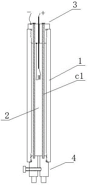
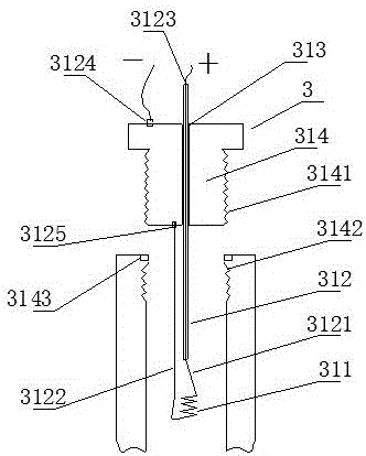
[0095] A gas blasting detonator, such as figure 1 As shown, it includes a tube body 1, a filling cavity 2, an ignition mechanism 3, and an inflating mechanism 4. The tube body 1 contains a filling cavity 2. The tube body 1 is hermetically connected to the ignition mechanism 3 and the inflation mechanism 4. The tube body 1 is resistant to pressure The strength is greater than 5.045Mpa; the tube body 1 is a carbon steel tube or a stainless steel tube, and the charging mechanism 4 and the ignition mechanism 3 are respectively connected to the two ends of the tube body 1; the filling cavity 2 is filled with a reducing agent and an oxidizing agent, the oxidizing agent It is liquid oxygen, supercritical oxygen or high-pressure gaseous oxygen, and the reducing agent is carbon-containing organic matter or reducing element.

[0096] With the above structure, the filling cavity 2 is pre-placed with a chemical agent in the solid oxidant or reducing agent. The solid-removing chemical agent ca...

Embodiment 2

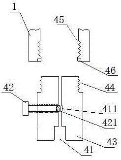
[0110] The difference from Example 1 lies in: Figure 4 As shown, the pipe body 1 includes a first section body 11 and a second section body 12. The first section body 11 and the second section body 12 are connected by a threaded structure, and are fitted with a threaded sealing ring 13 for connection. Seal; The inflation mechanism 4 and the ignition mechanism 3 are respectively connected to both sides of the first section body 11 and the second section body 11.

[0111] With this embodiment, when the tube body 1 is filled with solid materials, the first section body 11 and the second section body 12 are twisted apart and put in from the middle part as a whole. After placement, the first section body 11 and The second segment body 12 is twisted, and this structure is convenient for charging.

Embodiment 3

[0113] The difference from Example 1 lies in: Figure 5 As shown, the pipe body 1 is a composite layer cylinder containing fiber material. The pipe body 1 includes a base layer 101, a fiber layer 102 and a hardened layer 103. The hardened layer 103 is located on the outer layer of the fiber layer 102, and the base layer 101 is located on the fiber layer. 102 inner layer; one end of the tube body 1 is hermetically wrapped with a first metal joint 111, the other end of the tube body 1 is hermetically wrapped with a second metal joint 112, the first metal joint 111 is hermetically connected to the inflation mechanism 4, The two metal joints 112 are connected to the ignition mechanism 3 in a sealed manner; the bottoms of the first metal joint 111 and the second metal joint 112 protrude outward to avoid falling off from the tube body 1.

[0114] As a further description of the above embodiment, the base layer 101 is made of polyethylene (PE) material; the fiber layer 102 is made of gla...


PUM

PropertyMeasurementUnit
compressive strengthaaaaaaaaaa
thicknessaaaaaaaaaa
thicknessaaaaaaaaaa

Abstract

The invention discloses a gas blasting initiator and a fracturing device. The gas blasting initiator comprises a pipe body, a filling cavity, an ignition mechanism and an inflation mechanism, wherein the filling cavity is arranged in the pipe body; the pipe body is in sealing connection with the ignition mechanism and the inflation mechanism; the filling cavity is filled with supercritical oxygen and carbon-containing organic matters or reductive elementary substances; the ignition mechanism comprises a heating wire, a lead wire, a lead wire penetration hole and a sealing matrix; the heating wire is connected with the lead wire; the lead wire penetration hole is formed in the axis part of the sealing matrix; the lead wire penetrates through the lead wire penetration hole through an outer insulating layer; the inflation mechanism comprises an inflation hole, a valve rod and an inflation valve seat; the inflation hole is communicated with the inflation valve seat; a gas locking cavity is arranged at the middle of the inflation hole; the valve rod is mounted in the gas locking cavity; a connecting piece is connected between the inflation valve seat and the sealing matrix. The gas blasting initiator and the fracturing device have the advantages that the manufacture cost is low, the reaction material mixing uniformity is high, the heat release efficiency is high and the transport security is good.

Description

Technical field [0001] The invention belongs to the technical field of detonators, and particularly relates to a gas blast detonator and a cracker. Background technique [0002] Gas blasting technology uses the gasification and expansion of easily gasified liquid or solid materials to produce high-pressure gas, which causes the surrounding medium to expand and do work, and cause fragmentation. It has the characteristics of no open flame, safety and efficiency. [0003] Carbon dioxide gas blaster is a typical blasting equipment in gas blasting technology. It is widely used in mining, geological prospecting, cement, steel, electric power and other industries, subways and tunnels, municipal engineering, underwater engineering, and emergency rescue. [0004] The existing gas blaster mainly includes a vaporization liquid storage tube and a heating detonator installed in the vaporization liquid storage tube; the heating detonator ignites and generates heat to vaporize the easily vaporized ...

Claims


Application Information

Patent Timeline
Patent Type & Authority Applications(China)
IPC IPC(8): F42B3/04F42B3/10F42B3/103F42B3/11C06D5/10C06B47/12C06B47/06
CPCC06B47/06C06B47/12C06D5/10F42B3/04F42B3/10F42B3/103F42B3/11Y02P20/54
Inventor 郭远军
Owner 郭远军
Why Eureka
Try Eureka