Gas blaster igniter and cracker

A technology of detonating device and blaster, which is applied in the direction of valve device, blasting cylinder, compressed gas generation, etc. It can solve the problems of high manufacturing cost, low heat absorption efficiency of liquid carbon dioxide, and potential safety hazards, and achieve the effect of high mixing uniformity

Inactive Publication Date: 2017-05-10
郭远军
View PDF1 Cites 0 Cited by
  • Summary
  • Abstract
  • Description
  • Claims
  • Application Information

AI Technical Summary

Problems solved by technology

[0006] The detonating device with the above structure has the following problems: 1. The thermal reactants to be filled in the detonating device need to be processed by mixing, mixing, coiling or bagging, and the filling process is time-consuming. 2. During the filling process of the detonating device, the oxidant and reductant are prone to uneven mixing, resulting in low heat release efficiency; 3. The thermal reaction material needs to be mixed and filled in advance, and the temperature is too high during transportation. It is highly likely to cause combustion or explosion, and has a greater potential safety hazard; 4. Due to the delay of the detonating material or other situations, it is easy to appear the situation of squibs, and it is impossible to judge the cause of the squibs, so it cannot be eliminated by rowing the squibs Potential safety hazard; 5. The existing gas blaster detonation method uses a solid activator to burn to generate high temperature, which directly conducts heat to liquid carbon dioxide, causing the liquid carbon dioxide to gasify and expand, and its heat absorption efficiency of liquid carbon dioxide is low

Method used


Image

  • Gas blaster igniter and cracker
  • Gas blaster igniter and cracker
  • Gas blaster igniter and cracker

Examples


Embodiment 1

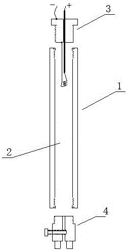
[0071] A gas blaster detonating device such as figure 1 As shown, it includes a housing 1, a filling chamber 2, an ignition mechanism 3 and an inflatable mechanism 4. The housing 1 is filled with a chamber 2, and the housing 1 is sealed to connect the ignition mechanism 3 and the inflatable mechanism 4. The pressure resistance of the housing 1 The strength is greater than 5.045Mpa; the shell 1 is a carbon steel cylinder or a stainless steel cylinder, and the inflation mechanism 4 and the ignition mechanism 3 are respectively connected to both ends of the shell 1;

[0072] With the above-mentioned structure, the filling chamber 2 is pre-placed with a chemical agent in the solid oxidant or reducing agent, and the de-solidified chemical agent can be in the form of powder, granule or filament; then, the gaseous or liquid state is filled by the inflation mechanism at the blasting site The oxidizing or reducing agent paired with the pre-placement. This structure can effectively avo...

Embodiment 2

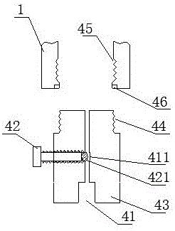
[0079] The difference with embodiment 1 is: as Figure 4 As shown, the housing 1 includes a first segment body 11 and a second segment body 12, the first segment body 11 and the second segment body 12 are connected through a threaded structure, and are matched with a threaded sealing ring 13 for Sealing; the inflation mechanism 4 and the ignition mechanism 3 are respectively connected to both sides of the first segment body 11 and the second segment body 11 .

[0080] Using this embodiment, when filling the shell 1 with solid material, the first segment body 11 and the second segment body 12 are twisted apart, put in from the middle as a whole, and after placing the first segment body 11 and the second segment body 12 The second segment body 12 is twisted, and this structure is convenient for charging.

Embodiment 3

[0082] The difference with embodiment 1 is: as Figure 5 As shown, the housing 1 is a composite layer tube containing fiber material, the housing 1 is made of composite layers, the housing 1 includes a matrix layer 101, a fiber layer 102 and a hardened layer 103, and the hardened layer 103 is located at The outer layer of the fiber layer 102, the matrix layer 101 is located in the inner layer of the fiber layer 102; the two ends of the housing 1 are respectively sealed and wrapped with a first metal joint 111 and a second metal joint 112, and the first metal joint 111 and the second metal joint 112 are sealed and wrapped respectively. Two metal joints 112 are respectively connected to the inflation mechanism 4 and the ignition mechanism 3 ;

[0083] As a further description of the above embodiment, the base layer 101 is made of polyethylene (PE); the fiber layer 102 is made of glass fiber; the hardened layer 103 is made of epoxy resin.

[0084] As a further description of the...


PUM

PropertyMeasurementUnit
Compressive strengthaaaaaaaaaa
Thicknessaaaaaaaaaa
Inner diameteraaaaaaaaaa

Abstract

The invention discloses a gas blaster igniter and a cracker. The gas blaster igniter comprises a shell, a filling cavity, an ignition mechanism and an inflation mechanism, wherein the filling cavity is formed in the shell, the shell is connected with the sealed ignition mechanism and the inflation mechanism, the ignition mechanism comprises a heating wire, a lead, a lead perforation and a sealed base body, the heating wire is connected with the lead, the axis part of the sealed base body is the lead perforation, and the lead wrapped by an insulating layer penetrates through the lead perforation; one end of the lead perforation is an inner threaded hole, an inner seal rubber ring is installed at the bottom of the inner threaded hole, the inner threaded hole is matched with a perforation screw, a perforation is formed in the axis of the perforation screw, the lead penetrates through the inner seal rubber ring and the perforation screw, and the perforation screw is matched with the inner threaded hole and compacts the inner seal rubber ring to seal a lead hole. The gas blaster igniter and the cracker have the advantages of low manufacturing cost, high reactant mixing uniformity, high heat release efficiency and good transport safety.

Description

technical field [0001] The invention belongs to the field of detonating devices, in particular to a detonating device for a gas blaster. Background technique [0002] Gas blasting technology is to use the vaporization and expansion of easily vaporized liquid or solid substances to generate high-pressure gas, which makes the surrounding medium expand to do work and cause fragmentation. It has the characteristics of no open flame, safety and high efficiency. [0003] Carbon dioxide gas blasters are typical blasting equipment in gas blasting technology, and are widely used in mining, geological exploration, cement, steel, electric power and other industries, subways and tunnels, municipal engineering, underwater engineering, and emergency rescue. [0004] Existing gas blasters mainly include a vaporization liquid storage pipe and a heating detonator installed in the vaporization liquid storage pipe; the heating detonation device ignites and generates heat to vaporize easily vap...

Claims


Application Information

Patent Timeline
IPC IPC(8): F42B3/04F42B3/10F42B3/103F42B3/11F42B3/18C06D5/10C06B33/00C06B47/12C06B47/06C06B47/02C06B27/00F16K15/02F16K24/06
CPCC06B27/00C06B33/00C06B47/02C06B47/06C06B47/12C06D5/10F16K15/02F16K24/06F42B3/045F42B3/10F42B3/103F42B3/11F42B3/18Y02P20/10
Inventor 郭远军
Owner 郭远军
Why Eureka
Try Eureka