A clamping fiber bragg grating temperature sensor and its application method

A temperature sensor, clip-on technology, applied to thermometers, thermometers with physical/chemical changes, instruments, etc., can solve the problems of low practicability

Inactive Publication Date: 2020-10-20
KUNMING UNIV OF SCI & TECH
View PDF6 Cites 0 Cited by
  • Summary
  • Abstract
  • Description
  • Claims
  • Application Information

AI Technical Summary

Problems solved by technology

When using fiber optic Bragg grating temperature sensors for temperature measurement, installation methods such as embedded, pasted, screw fixed, and manual fixed are often used. not very practical

Method used


Image

  • A clamping fiber bragg grating temperature sensor and its application method
  • A clamping fiber bragg grating temperature sensor and its application method
  • A clamping fiber bragg grating temperature sensor and its application method

Examples


Embodiment 1

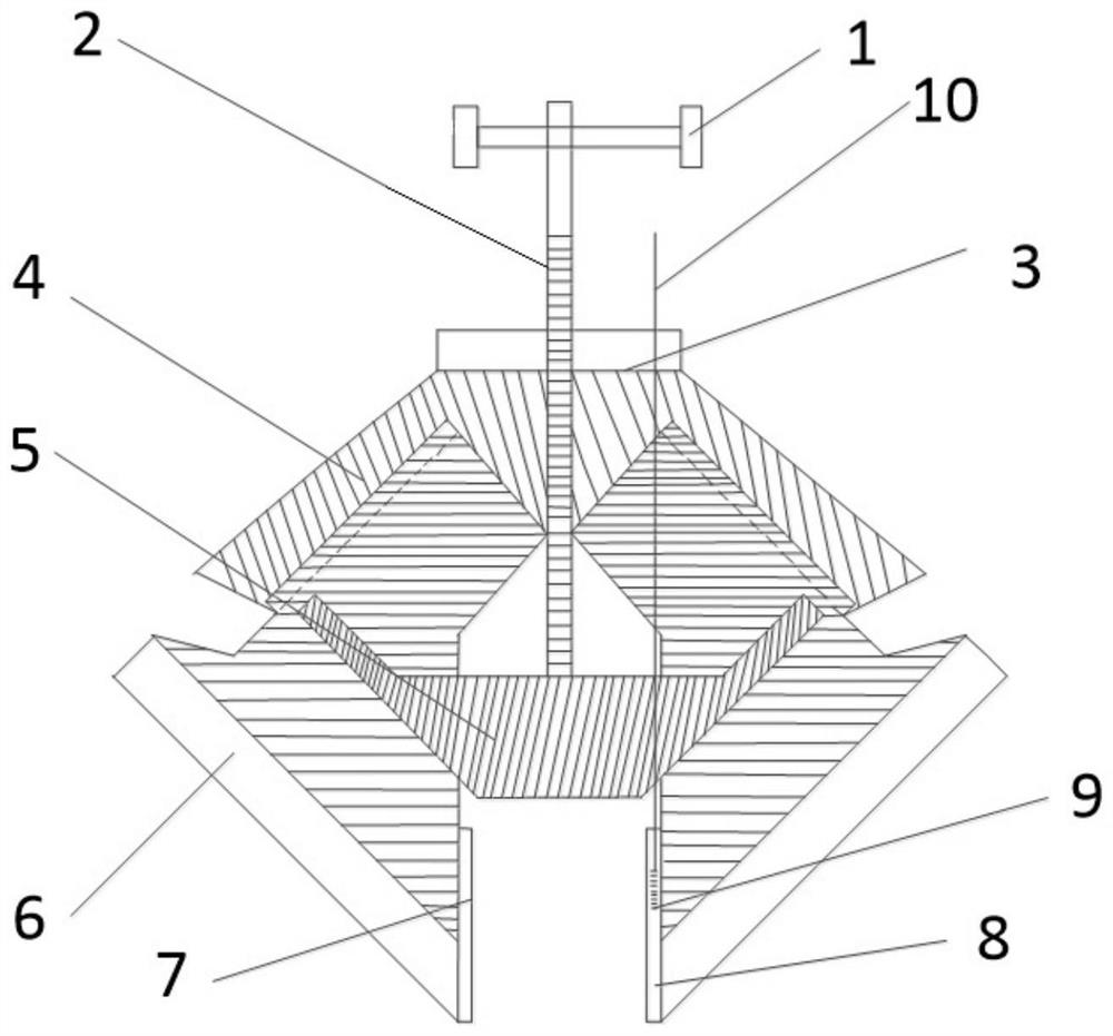
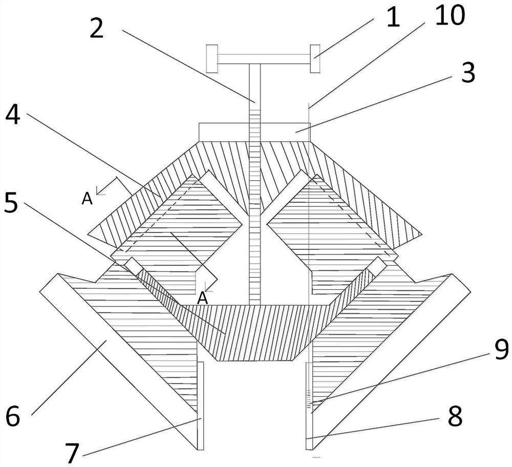
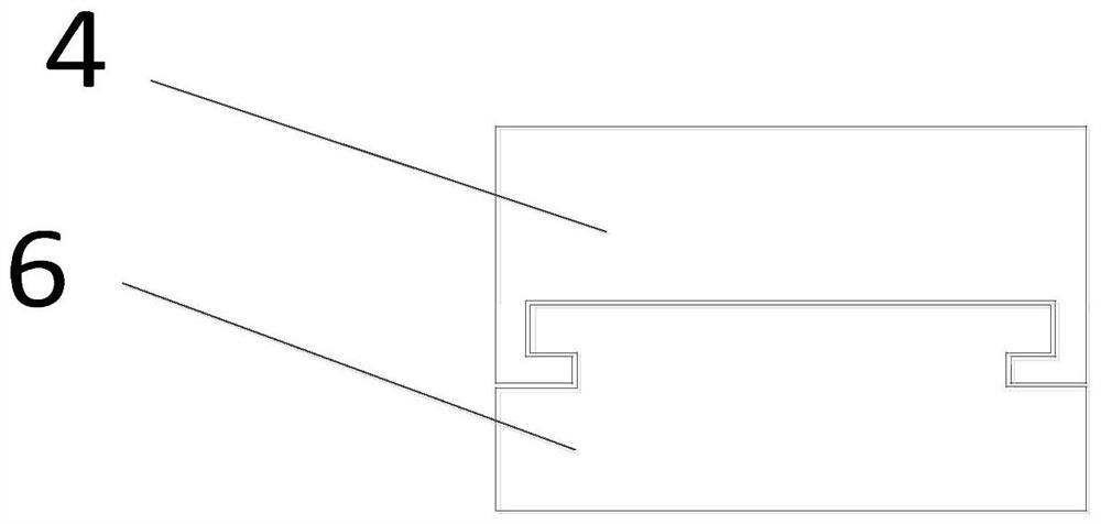
[0022] Embodiment 1: as Figure 1-3 As shown, a clamping optical fiber Bragg grating temperature sensor includes an adjustment rotating rod 1, a screw rod 2, a fixed block 3, a bottom plate 4, a control block 5, a clamp arm 6, a gasket 7, a polytetrafluoroethylene plate 8, an optical fiber Bragg grating 9, leading optical fiber 10; wherein the fixed block 3 is fixed on the base plate 4, the upper end of the clamp arm 6 is connected to the base plate 4, the upper end of the screw rod 2 is connected with the adjustment rotating rod 1, and the lower end passes through the fixed block 3 and the base plate 4 from top to bottom. It is connected with the top of the control block 5, the two ends of the control block 5 are provided with obliquely upward bosses, and the middle part of the clamp arm 6 is provided with jacks, and the two bosses of the control block 5 can be slidably inserted into the jacks of the left and right clamp arms 6 , and one side of the clamp arm 6 is provided wi...


PUM

PropertyMeasurementUnit
wavelengthaaaaaaaaaa

Abstract

The invention relates to a clamping optical fiber Bragg grating temperature sensor and a using method thereof, which belong to the technical field of optoelectronic measurement. The invention includes adjusting rotating rod, screw rod, fixing block, base plate, control block, clamp arm, spacer, polytetrafluoroethylene plate, optical fiber Bragg grating, and leading optical fiber; wherein the fixing block is fixed on the base plate, and the upper end of the clamp arm is connected to the base plate, The upper end of the screw is equipped with an adjustment rotary rod, the lower end is connected with the control block, the screw passes through the fixed block, the control block is connected with the left and right clamping arms, one side of the clamping arm is equipped with compression and high temperature resistant gaskets, and the other side is made of polytetrafluoroethylene plate, the fiber Bragg grating is packaged inside the polytetrafluoroethylene plate, and the leading optical fiber is drawn out along the top. According to the relationship between the shift value of the center wavelength of the fiber Bragg grating and the temperature of the measured object Δλ B = K T ΔT calculates the temperature of the measured object. The invention is suitable for temperature measurement of objects that can be clamped, has simple structure, is convenient for installation and disassembly, and has strong anti-interference ability.

Description

technical field [0001] The invention relates to a clamping optical fiber Bragg grating temperature sensor and a using method thereof, which belong to the technical field of optoelectronic measurement. Background technique [0002] In recent years, fiber optic sensors have been widely used in the field of measurement technology due to their advantages of high precision, low cost and strong anti-interference ability. Temperature is a common measurement item. At present, common temperature measurement tools include mercury thermometers, thermocouples, infrared temperature sensors, and fiber optic sensors. It has obvious comprehensive advantages in anti-corrosion and other aspects, especially when dealing with strong electromagnetic, flammable, explosive and other measurement environments. The fiber optic Bragg grating temperature sensor uses optical fiber materials, and optical signals are used in signal transmission and sensing. It realizes on-site non-electrical measurement ...

Claims


Application Information

Patent Timeline
Patent Type & Authority Patents(China)
IPC IPC(8): G01K11/32G01K11/3206
Inventor 张长胜刘畅李川赵振刚李英娜张家洪李伟谢涛刘爱莲万小容杨秀梅
Owner KUNMING UNIV OF SCI & TECH
Why Eureka
Try Eureka