Method and device for detecting clamping performance between vacuum electron device pipe casings and helical line

A vacuum electronic device and helix technology, which is applied in the field of optical fiber sensing and industrial measurement and control, can solve the problems of restricting output power, burning the helix, and rising temperature of slow wave structure, so as to reduce production cost, improve yield and high sensitivity Effect

Active Publication Date: 2014-12-17
SOUTHEAST UNIV
View PDF7 Cites 0 Cited by
  • Summary
  • Abstract
  • Description
  • Claims
  • Application Information

AI Technical Summary

Problems solved by technology

The slow-wave structure mainly conducts heat outward in the form of conduction. These losses cause a large heat flow rate in this part, which leads to an increase in the temperature of the slow-wave structure, which seriously affects the stability and reliability of the slow-wave structure and restricts its output power. transmission, when the heat loss is too large, it will even burn the helix

Method used


Image

  • Method and device for detecting clamping performance between vacuum electron device pipe casings and helical line

Examples


Embodiment Construction

[0023] The technical content of the present invention will be described in detail below in conjunction with the accompanying drawings.

[0024] A method for detecting the clamping property between the vacuum electronic device shell and the helix of the present invention, the method comprises the following steps:

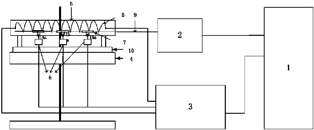
[0025] The first step: place the optical fiber sensor 7 in the optical fiber line 9 in the inner cavity of the helix 6, make the optical fiber sensor 7 contact the inner wall of the helix 6, and then connect one end of the optical fiber line 9 to the optical port of the demodulator 2 connect.

[0026] The second step: fix the temperature sensor 8 on the outer wall of the vacuum electronic device shell 5, and make the probe of the temperature sensor 8 contact with the vacuum electronic device shell 5, and the probe of the temperature sensor 8 is in contact with the vacuum electronic device shell 5 The contact point between and the contact point between the optical fi...


PUM


Abstract

The invention discloses a method for detecting clamping performance between vacuum electron device pipe casings and a helical line. The method comprises a first step of arranging an optical fiber sensor in the helical line, and enabling an optical fiber line to be connected with a demodulator; a second step of fixing a temperature sensor; a third step of enabling the temperature sensor, the demodulator, a personal computer (PC), the helical line and a main controlling machine to be connected; a fourth step of obtaining a mean temperature difference curve S<0> of N vacuum electron devices good in clamping performance; a fifth step of obtaining a temperature difference curve Q of to-be-measured vacuum electron devices; and a sixth step of judging the clamping performance between pipe casings of the to-be-measured vacuum electron devices and the helical line. A device for implementing the method comprises the PC, the demodulator, the main controlling machine, a beam and a detection unit. The detection unit comprises the vacuum electron device pipe casings, the optical fiber sensor and the temperature sensor. By utilizing the method and the device, measurement of the clamping performance of a designated position can be achieved on the premises that the vacuum electron devices are not damaged.

Description

technical field [0001] The invention belongs to the fields of optical fiber sensing and industrial measurement and control, and specifically relates to a method and a device for detecting the clamping property between a vacuum electronic device shell and a helix. Background technique [0002] Vacuum vacuum electronic devices are the core components of spaceborne transponders and spaceborne synthetic aperture radar transmitters, so they are known as the "heart" of satellite communication systems. With the rapid development of satellite communications, vacuum vacuum electronic devices have been more and more widely used, and higher and higher requirements are put forward for their reliability and lifespan. The high-reliability and long-life design of vacuum vacuum electronic devices is a technical problem concerned by the whole world. It is directly related to the stability and service life of the entire satellite communication system, and the reliability and life of vacuum va...

Claims


Application Information

Patent Timeline
Patent Type & Authority Patents(China)
IPC IPC(8): G01N25/20
Inventor 韦朴孙小菡朱露
Owner SOUTHEAST UNIV
Why Eureka
Try Eureka