Electric brush structure installed in slide wire current collector

A current collector and sliding contact wire technology, applied in the field of brush structure, can solve the problems that the brush is easily skewed to one side, difficult to ensure uniformity, unfavorable for stable and reliable power supply, etc., and achieves convenient and reliable installation and fixation. Smooth and smooth telescopic motion

Pending Publication Date: 2019-05-17
福建隆融机电设备有限公司
View PDF0 Cites 3 Cited by
  • Summary
  • Abstract
  • Description
  • Claims
  • Application Information

AI Technical Summary

Problems solved by technology

In this structure that uses a compression spring to push the brush, the contact pressure will change with the change of the stretching stroke of the compression spring. During the lifting and lowering movement of the construction elevator, the brush and the trolley line are affected by the machining accuracy and installation accuracy. Affected, the distance between the contact surface of the brush and the trolley line is difficult to ensure uniformity, so the telescopic stroke of the compression spring driving the brush is also constantly changing, resulting in the contact pressure between the brush and the trolley line is also Fluctuating, the change of contact pressure is easy to aggravate the wear of brushes, and it is not conducive to stable and reliable power supply
[0004] In addition, since the collector needs to slide as a whole while the brush is continuously expanding and contracting in the collector, the brush will continue to be subjected to the lateral force exerted by the trolley line guide rail during the stretching movement, so reliable guidance is required to ensure The brushes can be stretched stably, but the existing current collectors usually only have one guiding groove to install the brushes, the guiding effect is poor, the brushes tend to be skewed to one side, and the wear of the brushes is easily aggravated. Brush dust will further accumulate between the collector and the brush, further affecting the use of the brush

Method used


Image

  • Electric brush structure installed in slide wire current collector
  • Electric brush structure installed in slide wire current collector
  • Electric brush structure installed in slide wire current collector

Examples


Embodiment

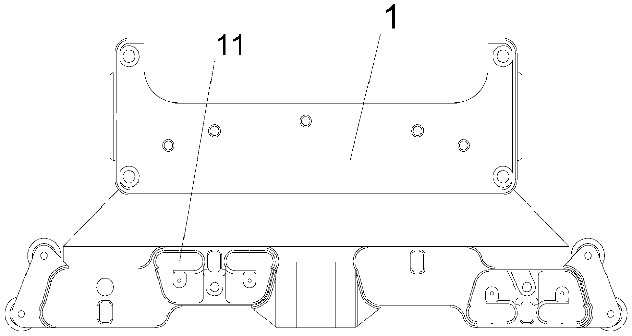
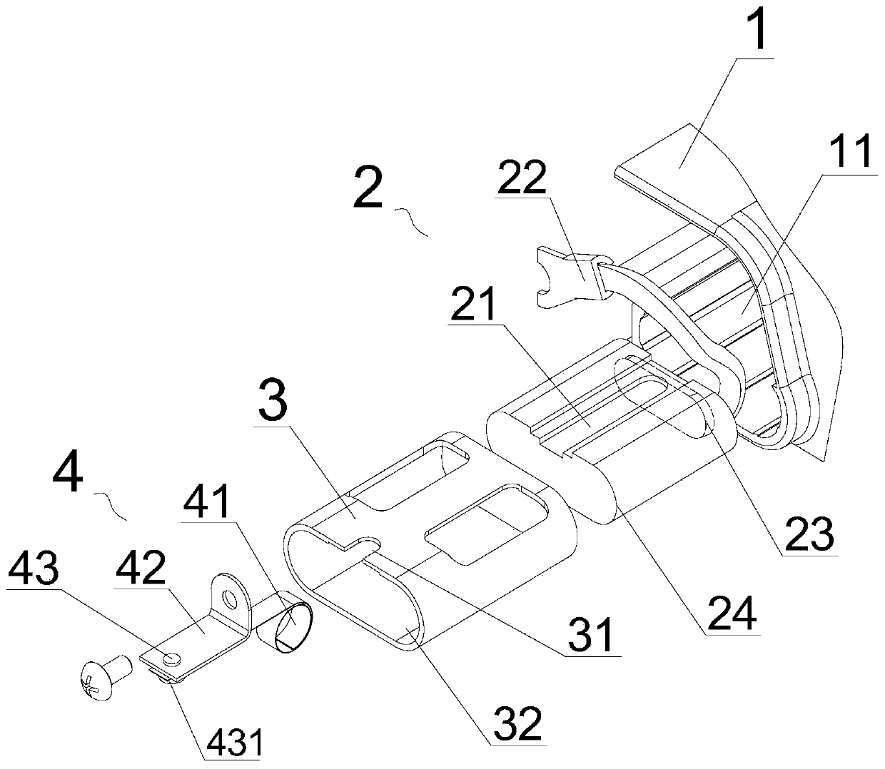
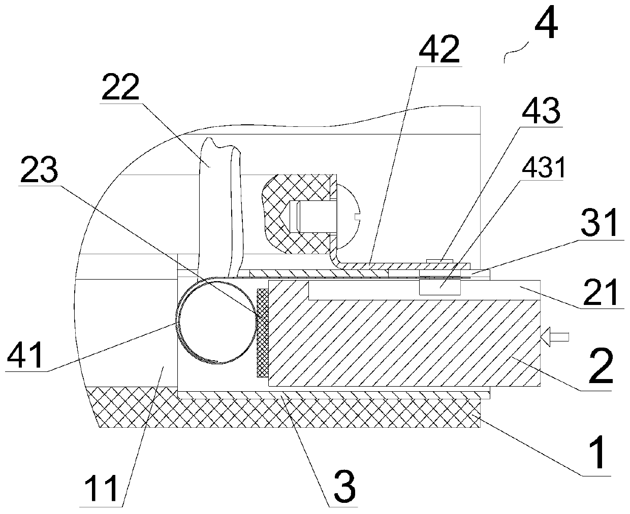
[0033] see Figure 1~5 As shown, a brush structure installed in a trolley line collector according to the present invention includes a collector housing 1 and a brush 2 installed in the collector housing 1, and the collector housing 1 There is more than one brush fixing groove 11 in the center, and a guide brush holder 3 is fixed in the brush fixing groove 11, and an open groove 31 is arranged on one side of the guide brush holder 3, and the open groove 31 The middle card is provided with a constant force driving spring assembly 4, and the constant force driving spring assembly 4 includes a constant force coil spring 41 and an L-shaped fixed bracket 42, and the end of the constant force coil spring 41 and the L-shaped fixed bracket One end of 42 is riveted together by rivet 43, the constant force coil spring 41 is placed in the cavity of the guide brush holder 3, and the other end of the L-shaped fixing bracket 42 is fixed in the collector housing 1 The electric brush 2 is al...


PUM


Abstract

The invention discloses an electric brush structure installed in a slide wire current collector and relates to the technical field of slide wires. The electric brush structure comprises a current collector shell and an electric brush; an electric brush fixing groove is formed in the current collector shell, a guide brush holder is fixed in the electric brush fixing groove, an opening groove is formed in one side of the guide brush holder, a constant force driving spring assembly is clamped in the opening groove, the constant force driving spring assembly comprises a constant force coil springand an L-shaped fixed support which are riveted together through rivets, the constant force coil spring is placed in a cavity of the guide brush holder, the electric brush is further arranged in the cavity of the guide brush holder in a sliding mode, the constant force coil spring contacts and abuts against the bottom surface of the electric brush, a guide sliding chute is formed in one side of the electric brush, and the guide sliding chute is in sliding fit with the head of a cylindrical end of the rivet. According to the electric brush structure in the invention, the electric brush can be well guided during telescopic motions, the electric brush is not prone to skewing and jamming, and the electric brush is not easy to wear; the constant force spring driving structure can provide balanced driving force, thereby facilitating stable and reliable power supply of the slide wire in the moving process.

Description

technical field [0001] The invention relates to the technical field of trolley lines, in particular to a brush structure installed in a trolley line collector. Background technique [0002] In the process of building construction, it is necessary to use the construction elevator to transport materials. The construction elevator needs to be connected to the power line to be driven. However, in the construction process, there is usually no dedicated power supply line to supply power to the construction elevator. Usually, the sliding contact is used. The line supplies power to the construction elevator. The sliding contact line is a number of conductive tracks laid in parallel along the running track of the construction elevator. The construction elevator is installed with a collector that can slide to connect the conductive track and take electricity. The sliding cooperation of the contact wires can provide uninterrupted power supply to the lifting and moving construction elev...

Claims


Application Information

Patent Timeline
Patent Type & Authority Applications(China)
IPC IPC(8): H01R41/00
Inventor 章永明刘学郭淑清林梦洁
Owner 福建隆融机电设备有限公司
Why Eureka
Try Eureka