Active-passive mixer

A mixer and main body technology, applied in the field of active-passive mixers, can solve the problems of limited fluid pumping energy, inability to accurately control the pumping volume, and the mixing effect and mixing ratio accuracy of piezoelectric fluid mixers need to be further improved. , to achieve the effect of strong fluid conveying capacity, good mixing effect and high proportioning accuracy

Active Publication Date: 2019-05-21
ZHEJIANG NORMAL UNIVERSITY
View PDF7 Cites 0 Cited by
  • Summary
  • Abstract
  • Description
  • Claims
  • Application Information

AI Technical Summary

Problems solved by technology

Existing piezoelectric active mixers basically use a single piezoelectric vibrator as a transducer to simultaneously realize the dual functions of fluid pumping and mixing. The fluid pumping energy is limited, and it cannot be used for high fluid viscosity, large pipeline flow resistance or Occasions that require a large amount of mixed fluid delivery: In addition, the existing piezoelectric fluid mixer uses the same transducer to synchronously drive two fluids with different viscosities, that is, the fluid is sucked in through the two inlets of the same chamber at the same time, and it is impossible to accurately control the two fluids. The pumping volume of a fluid
Obviously, the driving ability, mixing effect and mixing ratio accuracy of piezoelectric fluid mixers need to be further improved.

Method used


Image

  • Active-passive mixer
  • Active-passive mixer
  • Active-passive mixer

Examples


Embodiment Construction

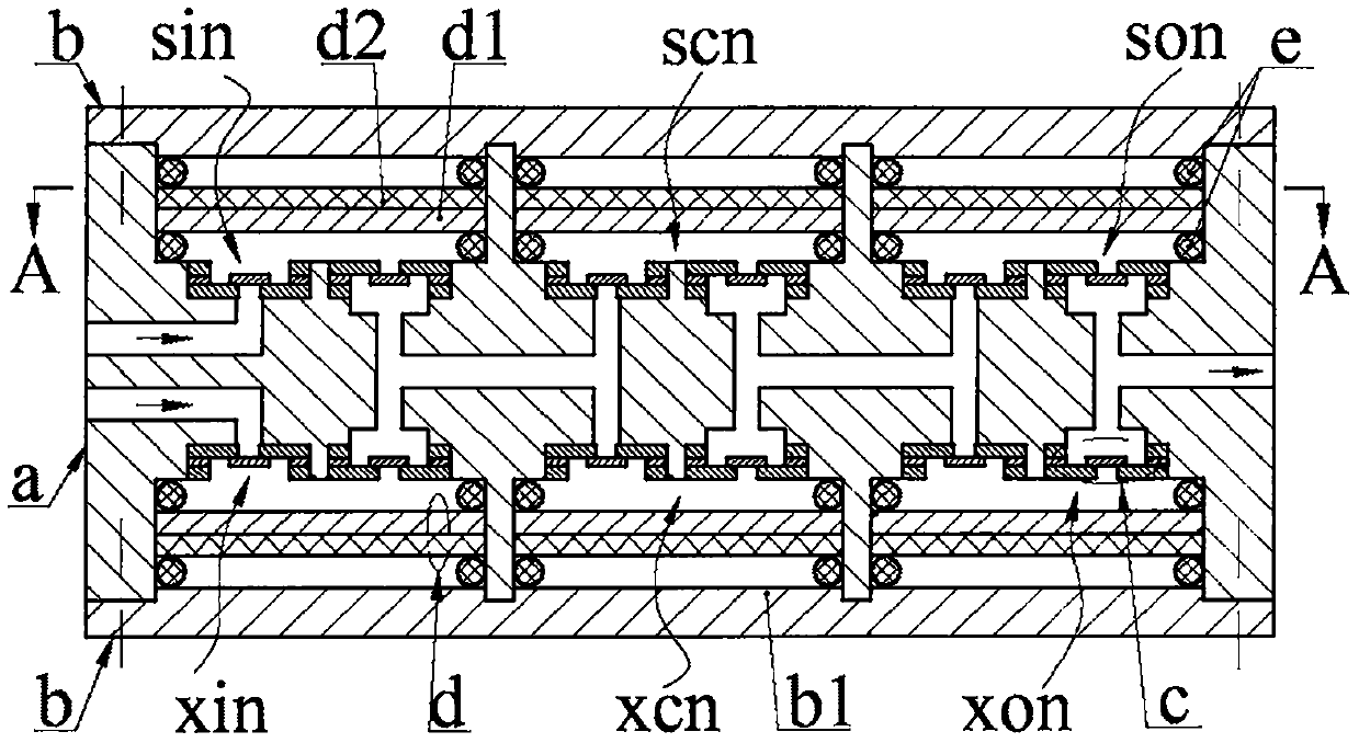
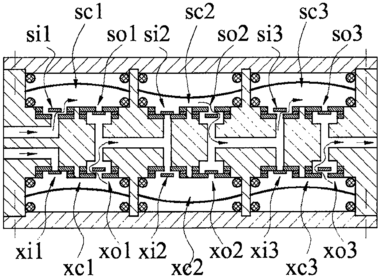
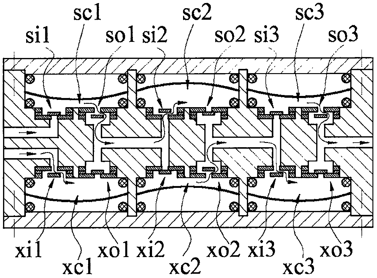
[0016] The main body a is provided with an upper inlet hole a1, a lower inlet hole a1', an outlet hole a2, an upper sinking cavity a3, and a sinking cavity a4. The trunking a5, the bottom wall of the upper sinking cavity a3 are provided with the upper inlet a6 and the upper outlet a7, and the top wall of the sinking cavity a4 is provided with the lower inlet a6' and the lower outlet a7'; The upper sinking cavity a3 and the lower sinking cavity a4 arranged laterally symmetrically constitute a sinking cavity group, and the upper inlet cavity a6 and the lower inlet cavity a6' of the leftmost sinking cavity group communicate with the upper inlet hole a1 and the lower inlet hole a1' respectively, and the last The upper outlet a7 and the lower outlet a7' of the right sunken cavity group are connected with the outlet a2, the upper inlet a6 and the lower inlet a6' of the other sunken cavity groups are connected through the inlet a8, and the upper outlet a7 and the lower outlet are conn...


PUM


Abstract

The invention belongs to the field of fluid driving and particularly relates to an active-passive mixer. End covers are mounted on the upper and lower sides of a main body, and transducers are pressedinto a main body sinking cavity through sealing rings; each transducer is formed by bonding a base plate with a piezoelectric sheet, and the piezoelectric sheets are mounted close to the end covers;upper and lower inlet cavities and one-way valves mounted in the upper and lower inlet cavities form upper and lower inlet valves respectively, and upper and lower outlet cavities and one-way valves mounted in the upper and lower outlet cavities form upper and lower outlet valves respectively; the transducers in upper and lower sinking cavity bodies, the main body and the sealing rings form upperand lower containing cavities respectively, the upper containing cavity and lower containing cavity in each sinking cavity group are connected in parallel to form a containing cavity group, and the two adjacent containing cavity groups in the left and right sides are connected in series. The upper containing cavity and lower containing cavity of each containing cavity group are crossed to suck anddischarge fluids, the discharged fluids are passively mixed through mixing holes, synchronously enter the upper containing cavity and lower containing cavity of the next containing cavity group for active mixing, and then enter other mixing holes for passive mixing after active mixing. The active-passive mixer has the advantages and characteristics that a mixing mode is combined with an active-passive mixing mode, the effect is good, the proportioning precision is high, and the pumping capacity is excellent.

Description

technical field [0001] The invention belongs to the field of fluid transmission and control, and in particular relates to an active-passive mixer. Background technique [0002] Fluid mixer is an indispensable key fluid control device in the fields of biochemistry, medical treatment, food, environmental monitoring and so on. Most of the original fluid mixers were passive, which changed the flow field distribution by setting special geometric structures in the fluid movement path and combined with the free diffusion of fluid molecules to achieve mixing. Its structure is simple, easy to manufacture and integrate, and its performance is stable. The disadvantage is that mixing The process is long, the speed is slow, and the mixing process is uncontrollable; in recent years, people have proposed various forms of active fluid mixers, which promote fluid mixing through external power. According to the source of power, the existing active mixers mainly include electromagnetic and Th...

Claims


Application Information

Patent Timeline
Patent Type & Authority Applications(China)
IPC IPC(8): B01F15/02B01F15/04B01F11/00F16K11/20F16K31/00
Inventor 阚君武吕鹏张子勍蔡建程王进程光明
Owner ZHEJIANG NORMAL UNIVERSITY
Why Eureka
Try Eureka